Loop heat pipe structure

A loop heat pipe and capillary structure technology, which is used in electrical equipment structural parts, cooling/ventilation/heating renovation, electrical components, etc., can solve the problems of poor heat dissipation, no pipe diameter space, and low density.

Pending Publication Date: 2018-03-23
ASIA VITAL COMPONENTS (CHINA) CO LTD
View PDF0 Cites 6 Cited by
  • Summary
  • Abstract
  • Description
  • Claims
  • Application Information

AI Technical Summary

Problems solved by technology

[0003] However, due to the above-mentioned known loop heat pipe structure, which is used to connect the pipe body of the evaporation chamber and the condensing device, it can be divided into a steam pipe from the evaporation outlet of the evaporating chamber to the condensing device, and a steam pipe from the condensing device to the evaporating chamber. There are two parts of the inlet liquid pipe, but since the pipe diameter is the same regardless of whether it is a steam pipe or a liquid pipe, there is no extra pipe diameter space for the working fluid of the gas phase to pass through, and because the working fluid of the gas phase has a low density , the same amount of working fluid in the gas phase and the working fluid in the liquid phase, the flow rate of the working fluid in the gas phase is smaller than the flow rate of the working fluid in the liquid phase, so that the flow rate of the working fluid in the liquid phase is larger than the flow rate of the working fluid in the gas phase , so that the steam in the evaporation chamber cannot pass through the steam pipe quickly to the condensing device for condensation into liquid, and the condensed liquid has flowed back into the evaporation chamber, and the steam in the evaporation chamber is blocked in the chamber, thus causing the overall Poor heat dissipation

Method used


Image

  • Loop heat pipe structure
  • Loop heat pipe structure
  • Loop heat pipe structure

Examples


Embodiment Construction

[0049] The above-mentioned purpose of the present invention and its structural and functional characteristics will be described based on the preferred embodiments of the accompanying drawings.

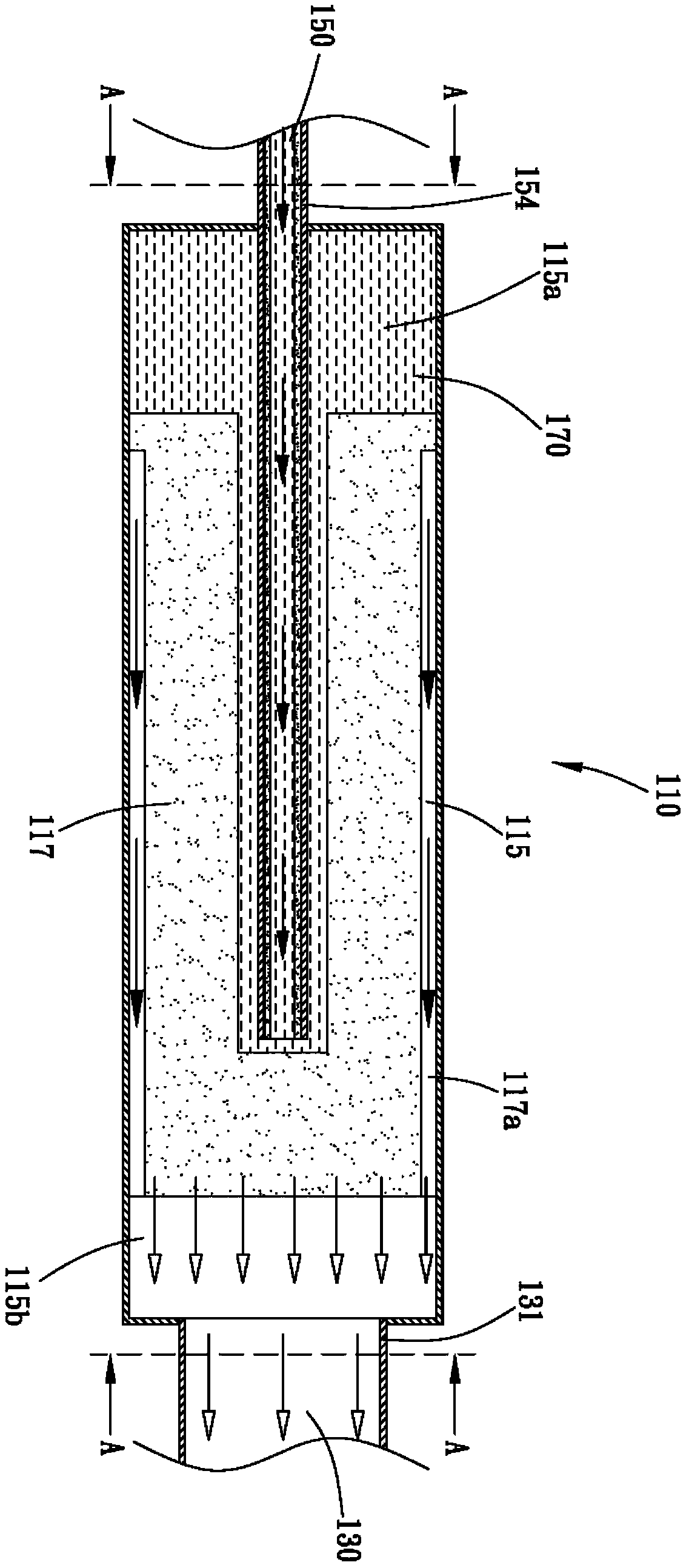
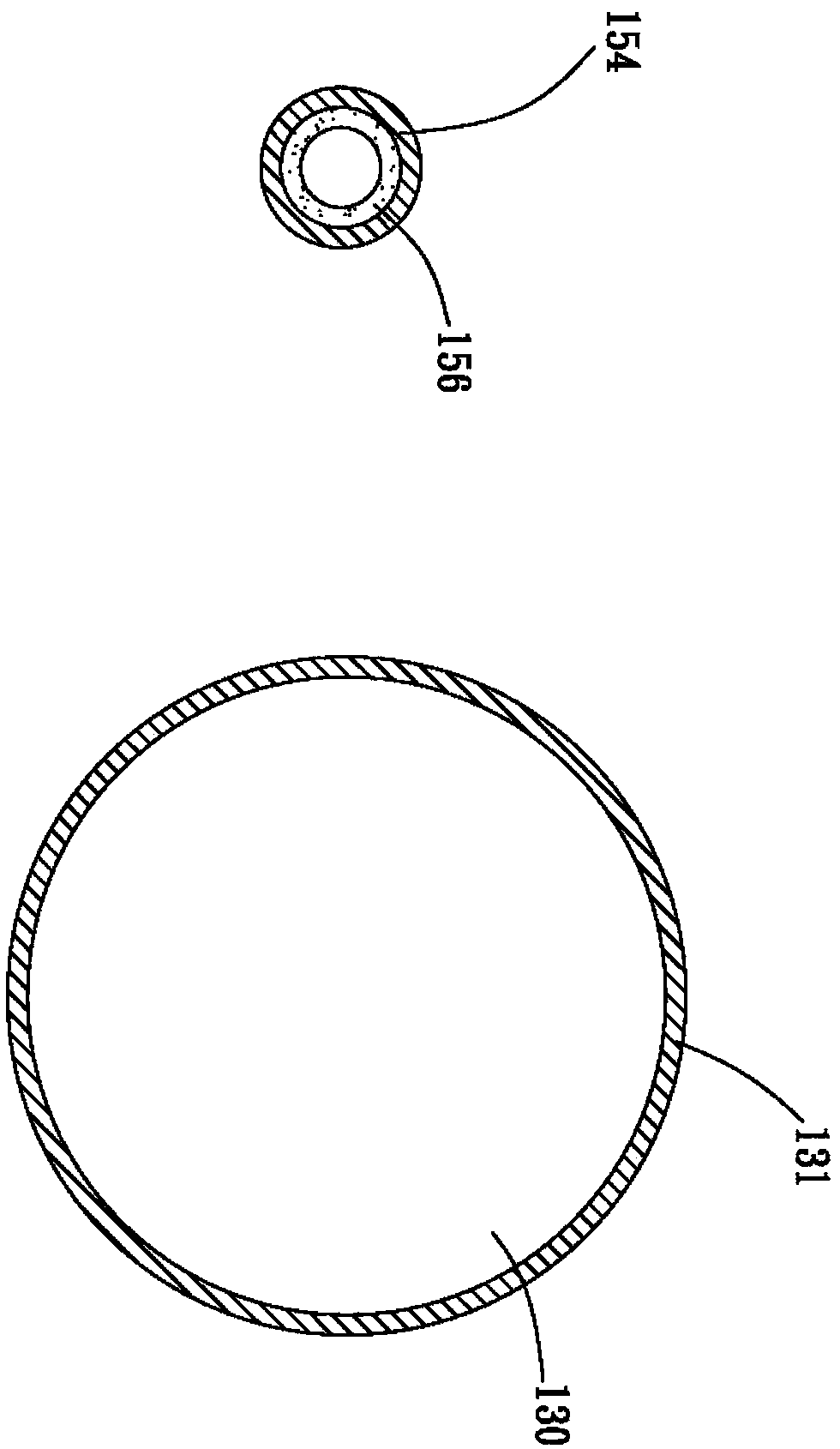
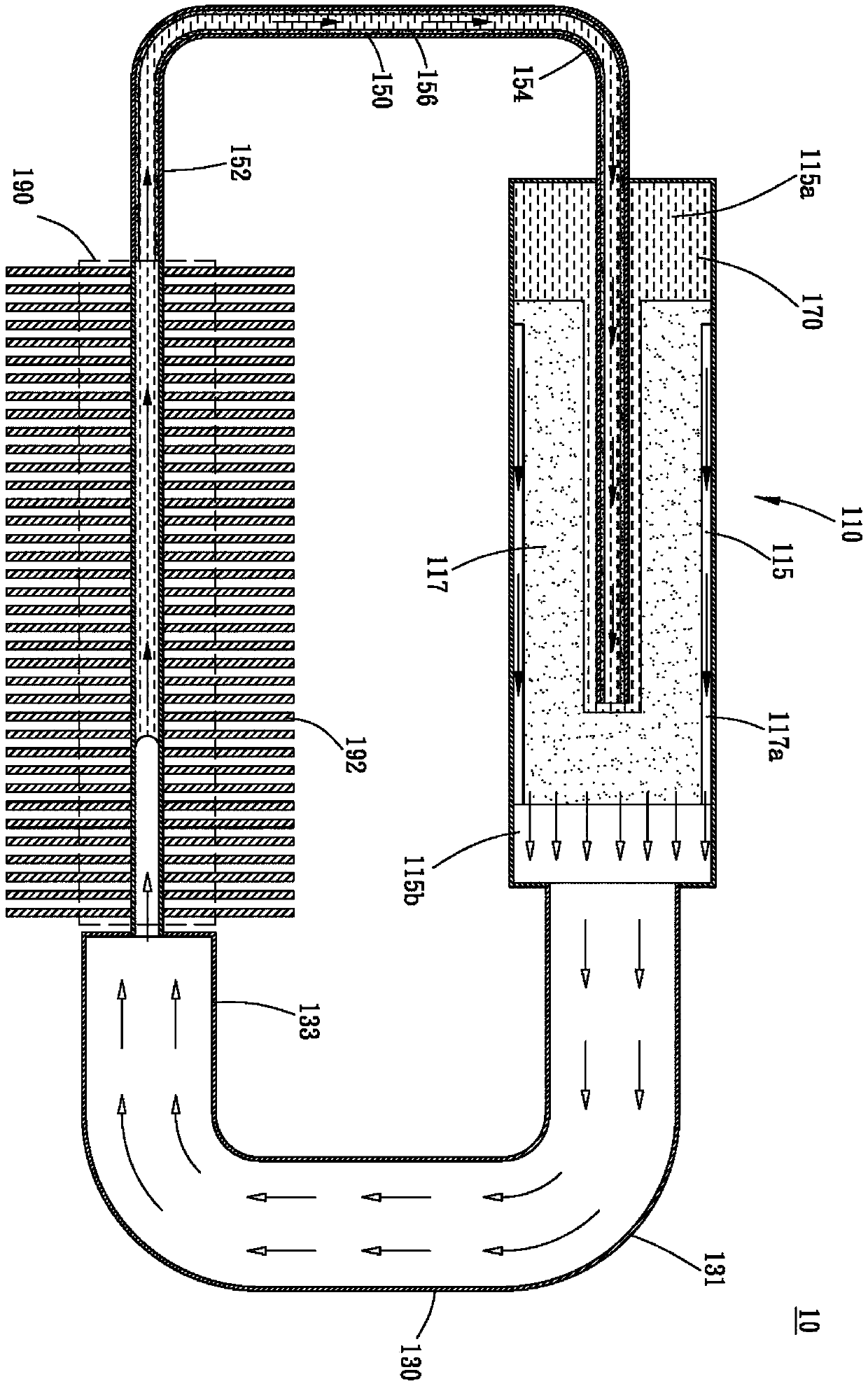
[0050] see figure 1 , 1a and figure 2 , is a schematic diagram of the evaporator of the first embodiment of the loop heat pipe structure of the present invention and a schematic diagram of the total pipe diameter A-A cross-sectional area of ​​a steam pipe and a liquid pipe and a top view sectional view, as shown in the figure, the loop heat pipe of the present invention The structure 10 includes an evaporator 110 , at least one vapor pipe 130 and at least one liquid pipe 150 .

[0051] The evaporator 110 has an evaporating cavity 115 , and the evaporating cavity 115 has a first capillary structure 117 and is filled with a working fluid 170 . In this embodiment, the first capillary structure 117 is shown as dividing and defining the evaporation chamber 115 into a liquid chamber 115a...


PUM


Abstract

A loop heat pipe structure comprises an evaporator, at least one steam pipe and at least one liquid pipe, wherein the evaporator possesses an evaporation chamber; a first capillary structure is arranged in the evaporation chamber and the evaporation chamber is filled with a work fluid; the steam pipe possesses a first end and a second end; the first end is connected to one end of the evaporation chamber; the liquid pipe possesses a third end and a fourth end; the third end is connected to a second end of the at least one steam pipe so as to form a condensation section; the fourth end is connected to the other end of the evaporator so as to form a loop of the work fluid; and a total pipe diameter section area of the steam pipe is greater than a total pipe diameter section area of the liquidpipe.

Description

【Technical field】 [0001] The invention relates to a loop heat pipe structure, in particular to a loop heat pipe structure capable of increasing the gas output of working fluid in the gas phase. 【Background technique】 [0002] Press, as the performance of current electronic equipment increases, the electronic components used to process signals and calculations generate relatively higher heat than previous electronic components. The most commonly used general heat dissipation components include heat pipes, radiators, and vapor chambers. and other components, and further increase the heat dissipation performance by directly contacting the electronic components that will generate heat, so as to prevent the electronic components from being burned due to excessive temperature. Furthermore, a fan with forced cooling effect is also installed to dissipate the heat of the cooling element. The fan can indeed improve the cooling performance, but not all fans can be installed in a limite...

Claims


Application Information

Patent Timeline
IPC IPC(8): H05K7/20
CPCH05K7/20336
Inventor 林源忆
Owner ASIA VITAL COMPONENTS (CHINA) CO LTD
Why Eureka
Try Eureka