Test tube clamping device

A clamping device and test tube technology, which is applied in the field of medical devices, can solve problems such as complex structure and bulky volume, and achieve the effects of simple control, quick and concise action, and easy implementation

Active Publication Date: 2018-03-27
HANGZHOU LONGXIN TECH
View PDF6 Cites 2 Cited by
  • Summary
  • Abstract
  • Description
  • Claims
  • Application Information

AI Technical Summary

Problems solved by technology

[0003] In order to solve the problems of complex structure and large volume in the prior art, the present invention provid

Method used


Image

  • Test tube clamping device
  • Test tube clamping device
  • Test tube clamping device

Examples


Embodiment Construction

[0029] The present invention will be further described below in conjunction with drawings and embodiments.

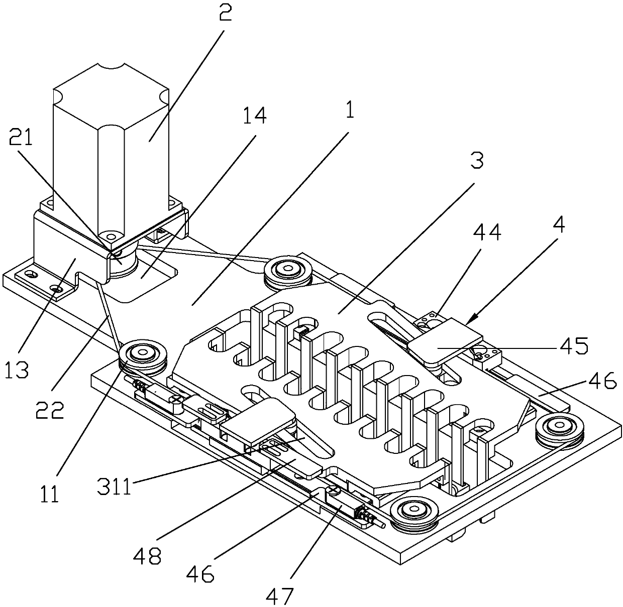
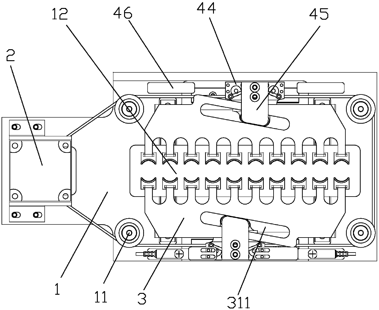
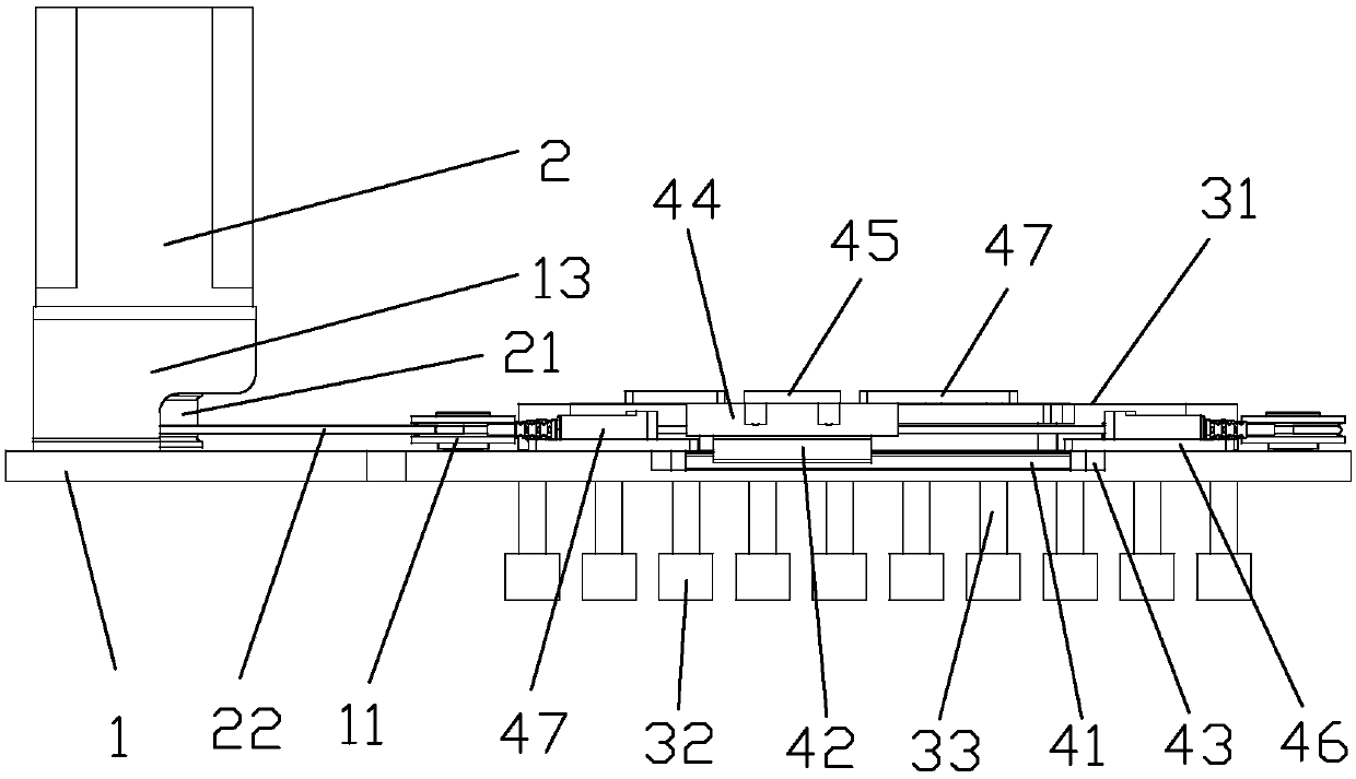
[0030] Such as figure 1 , figure 2 As shown, it is a test tube clamping device of the present invention, which includes a bottom plate 1 and a pair of clamping pieces 3, the clamping pieces 3 are arranged symmetrically on the right end of the bottom plate 1, and each clamping piece 3 is longitudinally slidably connected to the bottom of the bottom plate 1. On the surface, the top of the pipe clamping part 3 is provided with guide chute 311, and the center of the two guide chute 311 is distributed symmetrically. The bearing roller 441, the bearing roller 441 stretches into the guide chute 311 and is slidably connected with the guide chute 311, the base plate 1 is provided with guide wheels 11 on both sides of the top of the clamping pipe 3, and the left end of the base plate 1 is provided with a drive motor 2, Driving motor 2 is provided with driving wheel 21, and dri...


PUM


Abstract

The invention relates to the technical field of medical apparatus and instruments, and discloses a test tube clamping device. The test tube clamping device comprises a bottom plate and a pair of tubeclamping parts, wherein the tube clamping parts are symmetrically arranged at the right end of the bottom plate in a back and forth way; each tube clamping part is slidingly connected with the surfaceof the bottom plate along the longitudinal direction; the top part of each tube clamping part is provided with a guide inclined groove; the two guide inclined grooves are symmetrically distributed along the center; a transverse slide mechanism is arranged at the outer side of each tube clamping part on the bottom plate, and is provided with a bearing roll; each bearing roll extends into the corresponding guide inclined guide and is slidingly connected with the corresponding guide inclined groove; guide wheels are respectively arranged at both sides of the top end of each tube clamping part onthe bottom plate; a driving motor is arranged at the left end of the bottom plate; driving wheels are arranged on the driving motor; a driving rope is wound on the driving wheels, and sequentially passes through the driving wheels, the guide wheel and the transverse slide mechanism to form a sealed ring; each transverse slide mechanism is fixedly connected with the driving rope. The test tube clamping device has the advantages that a test tube can be accurately clamped; the structure is simple and compact, and the reliability is high.

Description

technical field [0001] The invention relates to the technical field of medical instruments, in particular to a test tube clamping device. Background technique [0002] Urine testing is a routine test in hospitals. The capped urine collection tube needs to be uncapped again during the inspection, which brings greater work intensity to the inspection operator. At the same time, unpleasant smell, dislocation of the sequence after opening the cap, and accidental pollution all affect the capping operation of the urinary tube. Higher requirements have been put forward, and there is no special urine collection tube capping machine to be used for urine collection tube cap removal at present. However, because of the complex structure and bulky size of the capping machine used for other items, it is not suitable for the clamping force of the urine collection tube. Contents of the invention [0003] In order to solve the problems of complex structure and large volume in the prior a...

Claims


Application Information

Patent Timeline
IPC IPC(8): B01L9/06
CPCB01L9/06
Inventor 姜文波王德正马勇男胡刚
Owner HANGZHOU LONGXIN TECH
Why Eureka
Try Eureka