
Smashed garbage processing structure

A technology of garbage disposal and crushing cavity, which is applied in grain processing, presses, chemical instruments and methods, etc., can solve the problems of unsatisfactory garbage crushing effect, large damage to crushing tools, and unfavorable garbage discharge, and achieves better discharge effect. Increase the effect of structural design and avoid discharge blockage

Inactive Publication Date: 2018-03-27
苏州拓洁环保工程有限公司
View PDF1 Cites 2 Cited by
  • Summary
  • Abstract
  • Description
  • Claims
  • Application Information

AI Technical Summary

Problems solved by technology

[0003] The technical problem mainly solved by the present invention is to provide a structure for crushing garbage, which solves the problems of unsatisfactory garbage crushing effect and great damage to the crushing tool by garbage, and also solves the problem that the original garbage auger is easy to block when discharging, which is not conducive to waste disposal problem

Method used

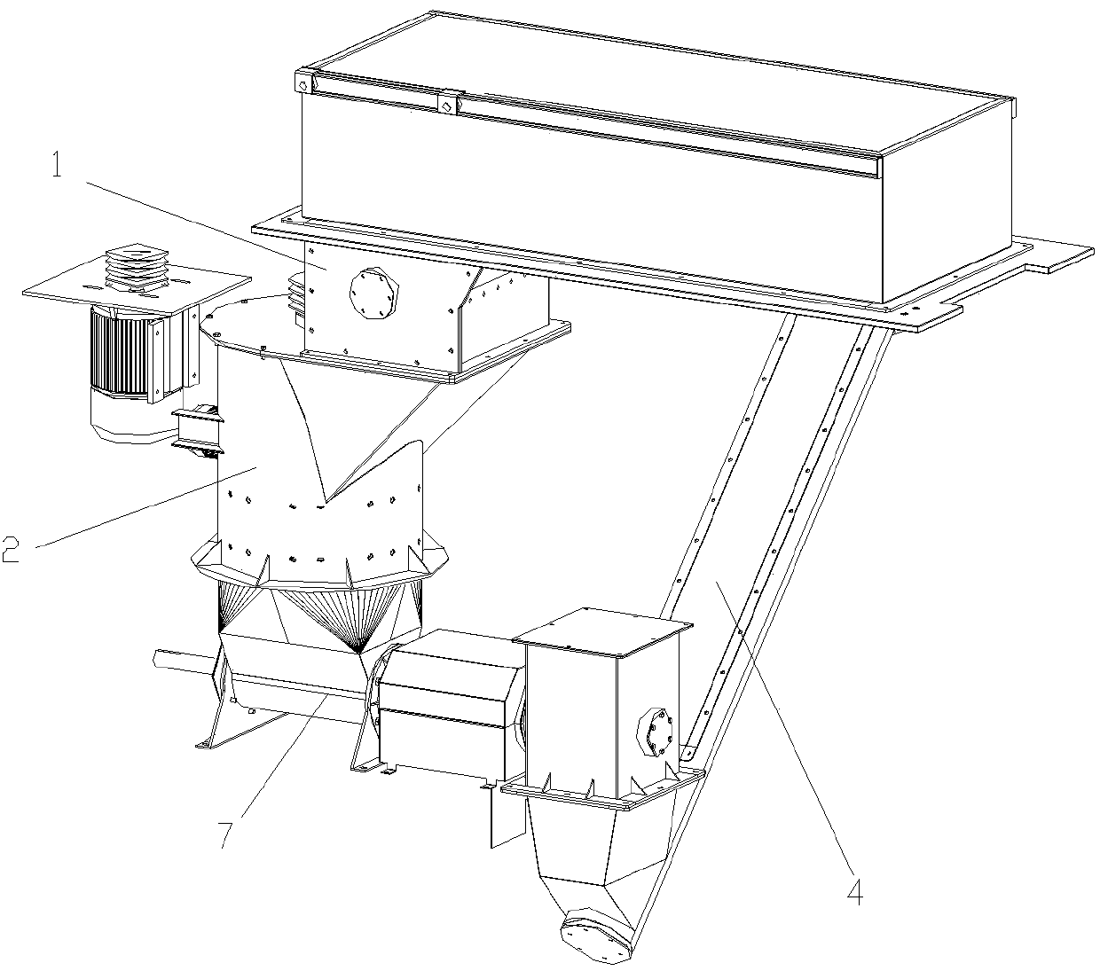
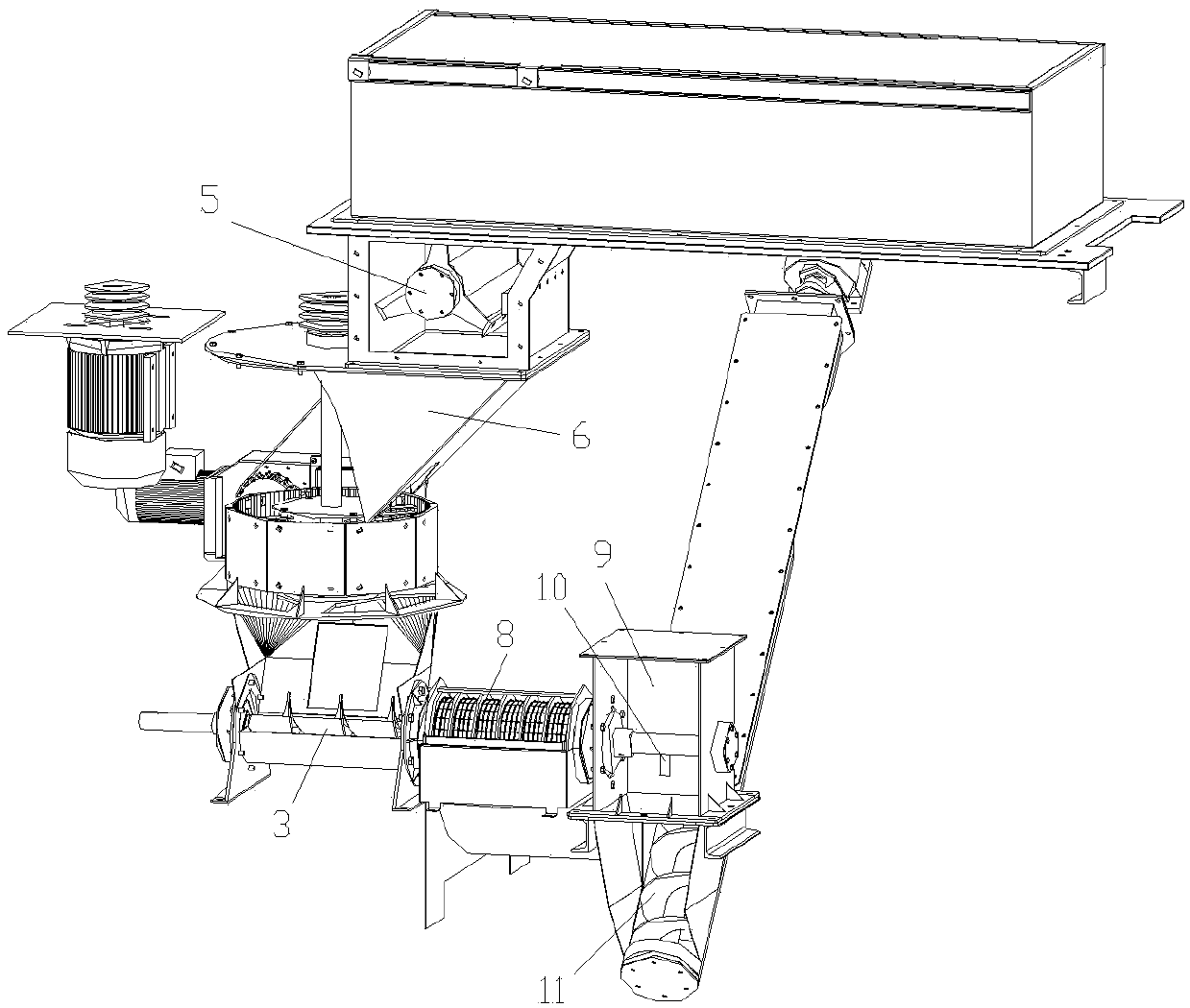
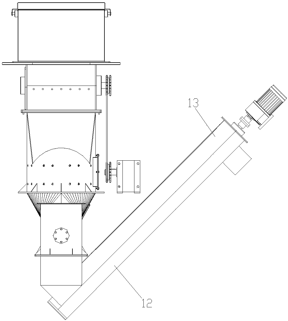

Image

  • Smashed garbage processing structure
  • Smashed garbage processing structure
  • Smashed garbage processing structure

Examples


Embodiment Construction

[0013] The preferred embodiments of the present invention will be described in detail below in conjunction with the accompanying drawings, so that the advantages and features of the present invention can be more easily understood by those skilled in the art, so as to define the protection scope of the present invention more clearly.

[0014] Please refer to the attached Figures 1 to 3 , the embodiment of the present invention includes:

[0015] A structure for crushing garbage, including a crushing chamber 1, a crushing chamber 2, layered cutters, a dehydrating auger 3, and a feeding channel 4. Garbage falls vertically in the crushing chamber 1, the entrance of the crushing chamber 1 is provided with a gentle slope for buffer discharge, and a crushing knife shaft 5 arranged on a horizontal axis is installed in the crushing chamber 1. The bottom outlet of the crushing chamber 1 is provided with a steep slope 6 for feeding. The gentle slope leads to the crushing knife shaft 5...


PUM


Abstract

The invention discloses a smashed garbage processing structure. The smashed garbage processing structure comprises a crushing cavity, a smashing cavity, a layered tool, a dehydrating packing auger anda loading channel, wherein garbage vertically drops into the crushing cavity; a crushing cutter shaft is transversely arranged in the crushing cavity; a slope surface for unloading is arranged at a bottom outlet of the crushing cavity; the bottom outlet of the crushing cavity communicates with the crushing cavity; the layered tool is vertically mounted in the crushing cavity; the bottom of the crushing cavity communicates with a packing auger of the dehydrating packing auger; the dehydrating packing auger further penetrates through a filter barrel to a pull-off cavity; the filter barrel communicates with a material cavity of the pull-off cavity; a rotary pull plate is fixedly arranged in the pull-off cavity; the pull plate rotates to crush blocked garbage which enters the pull-off cavity;the bottom of the pull-off cavity communicates with the loading channel; loading packing auger is arranged in the loading channel; and garbage is discharged from an upper-end outlet of the loading channel.

Description

technical field [0001] The invention relates to the field of garbage treatment equipment, in particular to a structure for crushing garbage. Background technique [0002] The garbage treatment device is mainly used for post-processing after the preliminary crushing of the garbage, so that the garbage can be better discharged to the outside world. For example, the Chinese invention patent "An Integrated Machine for Biochemical Treatment of Food Waste", whose application number is 201320649286.7, discloses a machine casing, a garbage collection device, an oil-water separation device, and a drying and decomposition device; the garbage collection device includes a garbage dumping mechanism and a sorting mechanism. platform; the dry decomposition device includes a decomposition mixing bucket and a suction structure; one side of the casing is equipped with a garbage dumping mechanism; the top of the casing is equipped with a sorting platform; the oil-water separation device, decom...

Claims


Application Information

Patent Timeline
Patent Type & Authority Applications(China)
IPC IPC(8): B09B3/00B02C18/14
CPCB02C18/14B02C18/18B09B3/00B09B5/00B30B9/14B09B2101/02
Inventor 尤俐
Owner 苏州拓洁环保工程有限公司
Learn More