Hoisting device for stirring cylinder

The technology of a hoisting device and a mixing tank is applied in the field of hoisting devices for a mixing tank, and can solve the problems of inconvenient hoisting of the mortar mixing tank and the like

Pending Publication Date: 2018-03-27
ANHUI XINGMA SPECIAL PURPOSE VEHICLE
View PDF4 Cites 6 Cited by
  • Summary
  • Abstract
  • Description
  • Claims
  • Application Information

AI Technical Summary

Problems solved by technology

[0005] In view of this, the object of the present invention is to provide a mixing tank hoisting device, which can effectively solve the problem of inconvenient hoisting of the mortar mixing tank

Method used


Image

  • Hoisting device for stirring cylinder
  • Hoisting device for stirring cylinder
  • Hoisting device for stirring cylinder

Examples


Embodiment Construction

[0024] The embodiment of the invention discloses a stirring tank hoisting device to effectively solve the problem of inconvenient hoisting of the mortar mixing tank.

[0025] The following will clearly and completely describe the technical solutions in the embodiments of the present invention with reference to the accompanying drawings in the embodiments of the present invention. Obviously, the described embodiments are only some, not all, embodiments of the present invention. Based on the embodiments of the present invention, all other embodiments obtained by persons of ordinary skill in the art without making creative efforts belong to the protection scope of the present invention.

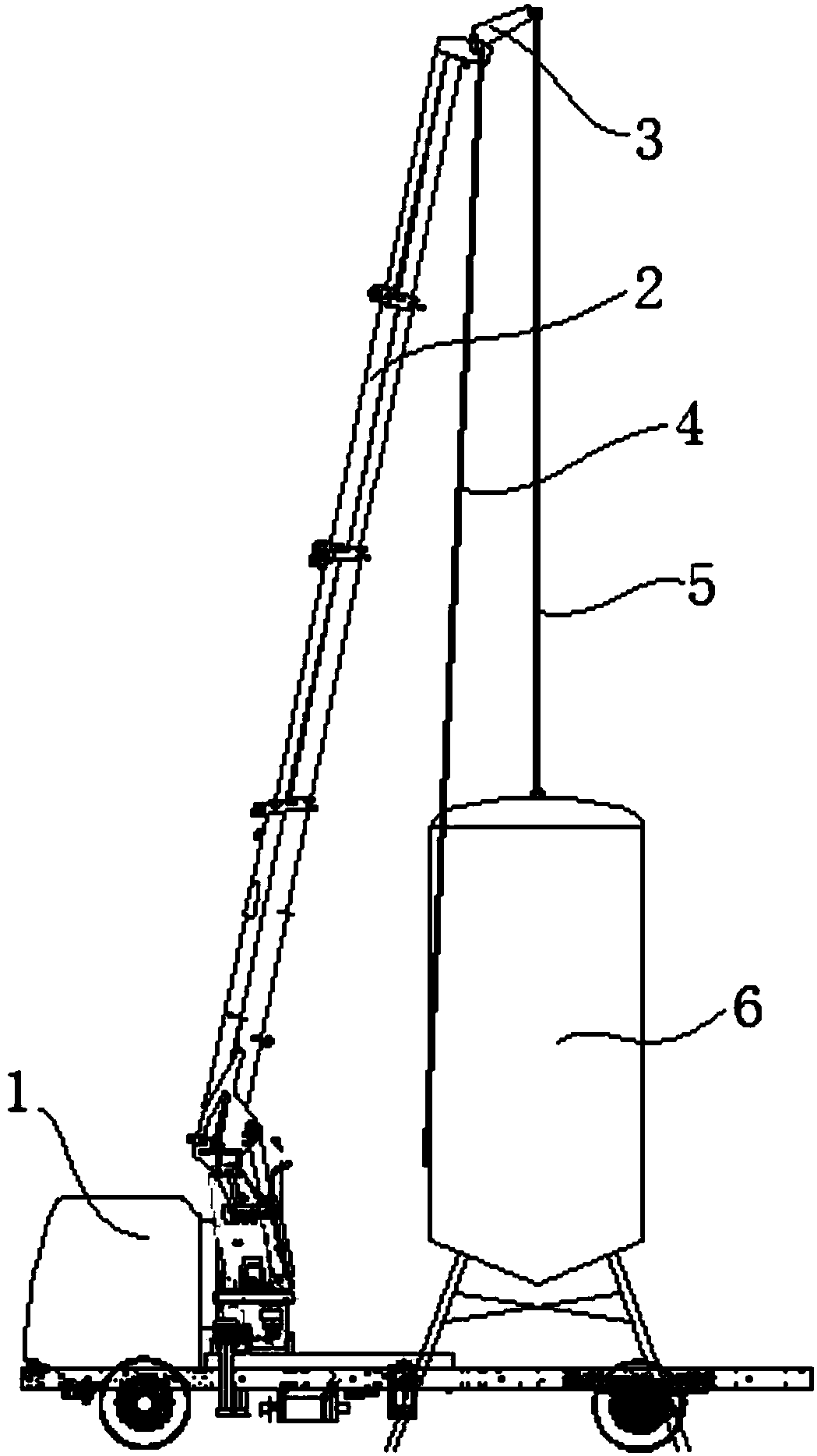
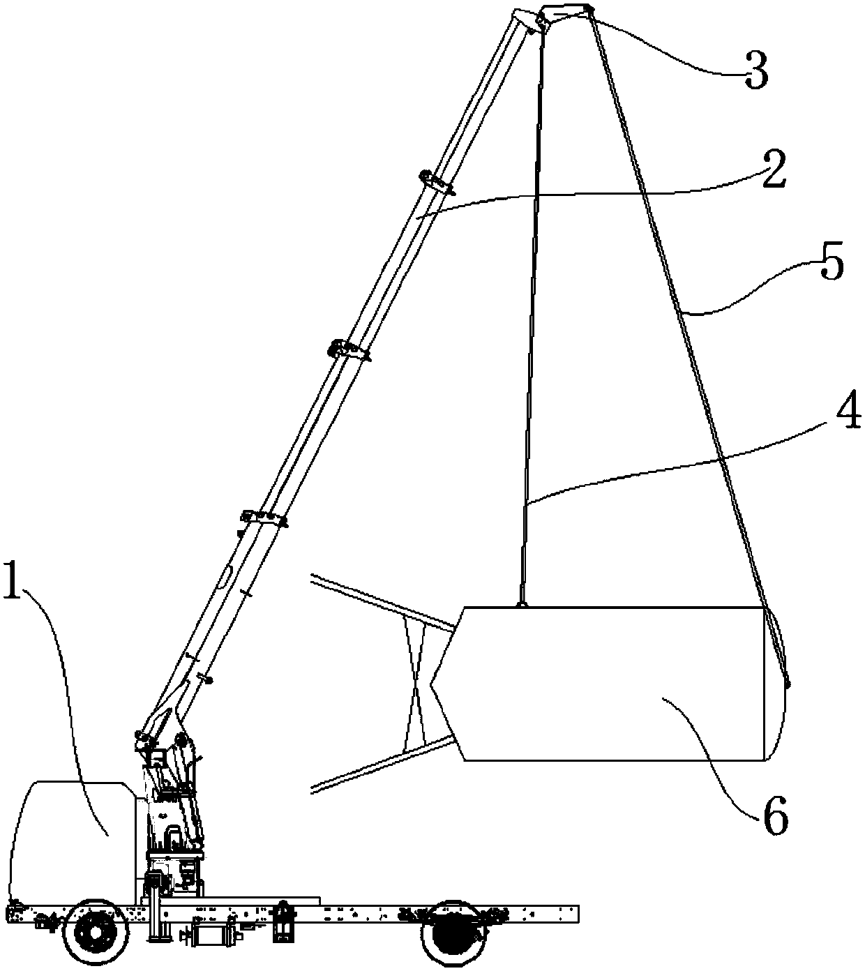
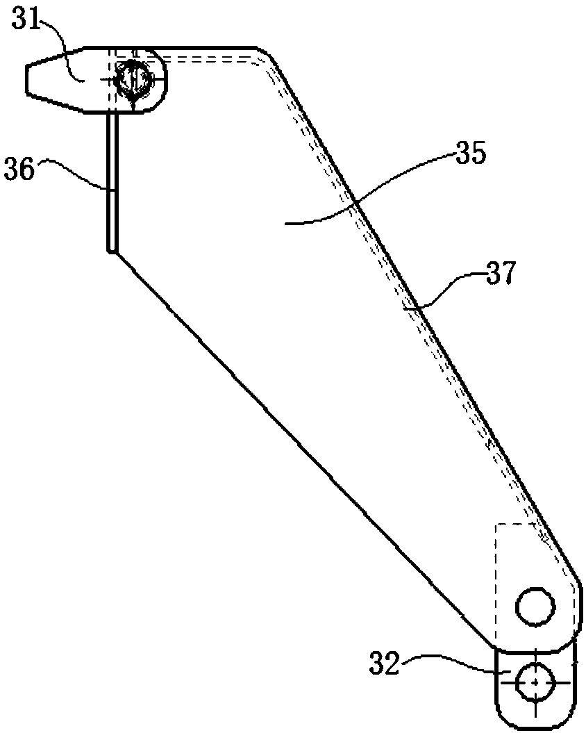
[0026] see Figure 1-Figure 4 , figure 1 It is a schematic diagram of the hoisting structure before hoisting of the hoisting device for the stirring tank provided by the embodiment of the present invention; figure 2 It is a schematic diagram of the hoisting structure of the hoisting device fo...


PUM


Abstract

The invention discloses a hoisting device for a stirring cylinder. The hoisting device comprises a base, a telescopic arm of which the bottom is arranged on the base, a hoisting base arranged on the telescopic end of the telescopic arm, a first hoisting rope which is wound on the hoisting base and a first hoisting device used for adjusting the length of the part, located between the hoisting baseand a hoisting part, of the first hoisting rope, the hoisting device further comprises a second hoisting rope of which one end can be fixed relative to the hoisting base; one end of the hoisting ropeis provided with the hoisting part; and the other end of the second hoisting rope is provided with a connection part which is connected with the stirring cylinder. In the hoisting device for the stirring cylinder, the second hoisting rope is additionally arranged, and the hoisting height of the first hoisting rope can be adjusted with cooperation with the first hoisting device, so that the vertical stirring cylinder can be hoisted to be horizontal, and the stirring cylinder can be conveniently hoisted and placed on a conveying truck horizontally; and then the problem that the stirring cylindercannot be hoisted and conveyed conveniently can be solved.

Description

technical field [0001] The invention relates to the technical field of engineering machinery, and more specifically, relates to a stirring tank hoisting device. Background technique [0002] Nowadays, the dry powder mortar mixing tanks commonly used in the market are generally in a cylindrical state, with a diameter of about 3 meters, a height of 8-15 meters, and a weight of 1-3 tons. In this way, the dry powder mortar mixing tank cannot be manually Finish. At present, there are many ways to lift the dry powder mortar mixing tank. The most common method is to use the back tank truck to transport the dry powder mortar mixing tank. [0003] It is a very fast and convenient method to transport with a tank truck, but only one dry powder mortar mixing tank can be transported at a time by using a tank truck, so if a lot of dry powder mortar mixing tanks are transported, each dry powder mortar mixing tank needs to be equipped with one Carrying a tanker, or using a tanker to trans...

Claims


Application Information

Patent Timeline
Patent Type & Authority Applications(China)
IPC IPC(8): B66C23/04B66C23/06B66C13/08
CPCB66C13/08B66C23/04B66C23/06
Inventor 王本路杨路朱保江梁兆义赵长金
Owner ANHUI XINGMA SPECIAL PURPOSE VEHICLE
Why Eureka
Try Eureka