Eureka AIR delivers breakthrough ideas for toughest innovation challenges, trusted by R&D personnel around the world.

A flatness detection device

A technology of flatness detection and mold detection, which is applied in the field of detection, can solve problems such as inability to carry out large-scale detection, long time required for detection of workpieces, deviation of detection results, etc., and achieve the effect of simple structure, high work efficiency and continuous detection

Active Publication Date: 2019-10-25
浙江省磐安县磐锋刀片有限公司
View PDF6 Cites 0 Cited by
  • Summary
  • Abstract
  • Description
  • Claims
  • Application Information

AI Technical Summary

Problems solved by technology

[0002] In the mechanical processing industry, the surface of the machined part or the surface of the die-casting or casting blank has technical requirements for its flatness, and it must be measured to determine whether it is qualified; the current relatively simple detection method is: select the workpiece to be tested. The opposite surface is the reference plane, and it takes a long time to detect the workpiece by using precision measuring tools such as vernier calipers and micrometers to measure the heights of multiple places on the plane to be measured; however, when the existing flatness detection device detects the workpiece, it takes a long time to detect the workpiece , it is impossible to carry out large-scale detection; the rapid and large-scale detection requirements required for production cannot be met, and there are deviations in the detection results; therefore, in order to solve the above problems, the present invention provides a flatness detection device

Method used


Image

  • A flatness detection device
  • A flatness detection device
  • A flatness detection device

Examples


Embodiment Construction

[0016] The present invention will be further described below in conjunction with the accompanying drawings.

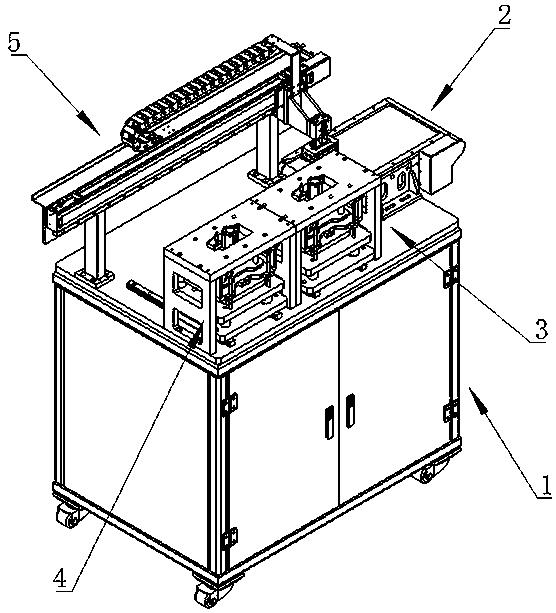
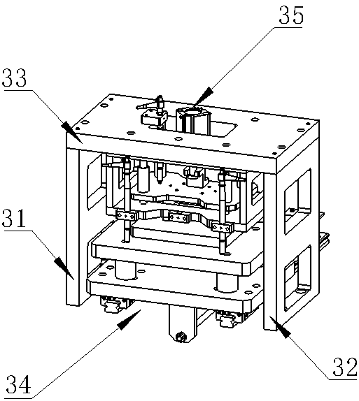
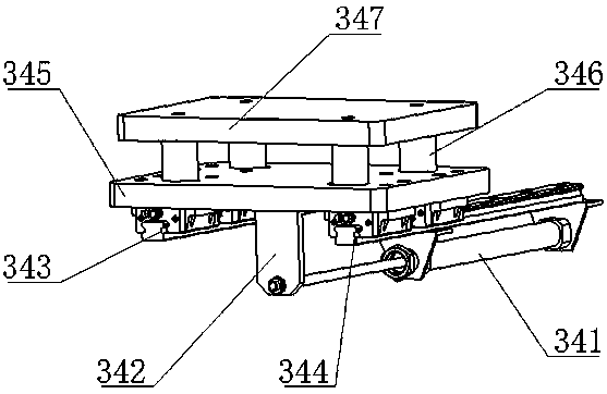
[0017] Such as figure 1 , figure 2 , image 3 , Figure 4 , Figure 5 As shown, a flatness detection device includes a frame 1, the right part of the upper surface of the frame 1 is provided with a feeding module 2, and the left side of the feeding module 2 is provided with a first detection module 3, The left side of the first detection module 3 is provided with a second detection module 4 with the same structure, and the rear of the first detection module 3 and the second detection module 4 is provided with a material transfer module 5, and the feeding module 2 Use the motor to drive the conveyor belt to load the material. The first detection module 3 is used for the first flatness detection, and the second detection module 4 is used for the second detection to ensure the accuracy of the detection. The material transfer module Group 5 is used for product displa...


PUM


Abstract

The invention discloses a flatness detection device. The device comprises a rack; a feeding module set is arranged at the right part of the upper surface of the rack; a first detection module set is arranged at the left side of the feeding module set; a second detection module set which is of the same structure as the first detection module set is arranged at the left side of the first detection module set; and a material shifting module set is arranged behind the first detection module set and the second detection module set. According to the feeding module, a conveyor belt is driven to perform feeding through a motor; the first detection module set is used for performing first flatness detection; the second detection module set is used for performing second detection so as to ensure theaccuracy of the detection; and the material shifting module set is used for shifting products between the feeding module set, the first detection module set, and the second detection module set. The flatness detection device of the invention has the advantages of simple structure, high work efficiency, and accurate detection results.

Description

technical field [0001] The invention relates to the technical field of detection, in particular to a flatness detection device. Background technique [0002] In the mechanical processing industry, the surface of the machined part or the surface of the die-casting or casting blank has technical requirements for its flatness, and it must be measured to determine whether it is qualified; the current relatively simple detection method is: select the workpiece to be tested. The opposite surface is the reference plane, and it takes a long time to detect the workpiece by using precision measuring tools such as vernier calipers and micrometers to measure the heights of multiple places on the plane to be measured; however, when the existing flatness detection device detects the workpiece, it takes a long time to detect the workpiece , it is impossible to perform large-scale detection; the rapid and large-scale detection requirements required for production cannot be met, and there ar...

Claims


Application Information

Patent Timeline
Patent Type & Authority Patents(China)
IPC IPC(8): G01B5/28
CPCG01B5/28
Inventor 代延召
Owner 浙江省磐安县磐锋刀片有限公司
Why Eureka
Eureka Blog
Learn More