
Lens and implementation method for internal gas heat balance

A thermal balance, lens technology, applied in the field of lenses, can solve problems such as lens damage, physical changes in space gas, blurring, etc.

Active Publication Date: 2018-03-27
NINGBO SUNNY AUTOMOTIVE OPTECH
View PDF10 Cites 2 Cited by
  • Summary
  • Abstract
  • Description
  • Claims
  • Application Information

AI Technical Summary

Problems solved by technology

The temperature change of each lens of the lens will cause thermal expansion and contraction of the lens, which may cause the lens to be out of focus and image blur; and the sudden temperature change of the different spaces formed by these lenses may easily cause physical changes in the space gas and affect the lens. Imaging effect
In addition, uneven heating of different parts of the lens may also make the lens more susceptible to damage

Method used


Image

  • Lens and implementation method for internal gas heat balance
  • Lens and implementation method for internal gas heat balance
  • Lens and implementation method for internal gas heat balance

Examples


Embodiment Construction

[0045] The following description is disclosed to enable any person skilled in the art to make and use the invention. The preferred embodiments provided in the following description are only examples and modifications obvious to those skilled in the art, and they are not intended to limit the scope of the present invention. The general principles defined in the following description may be applied to other embodiments, alternatives, modifications, equivalent implementations and applications without departing from the spirit and scope of the invention.

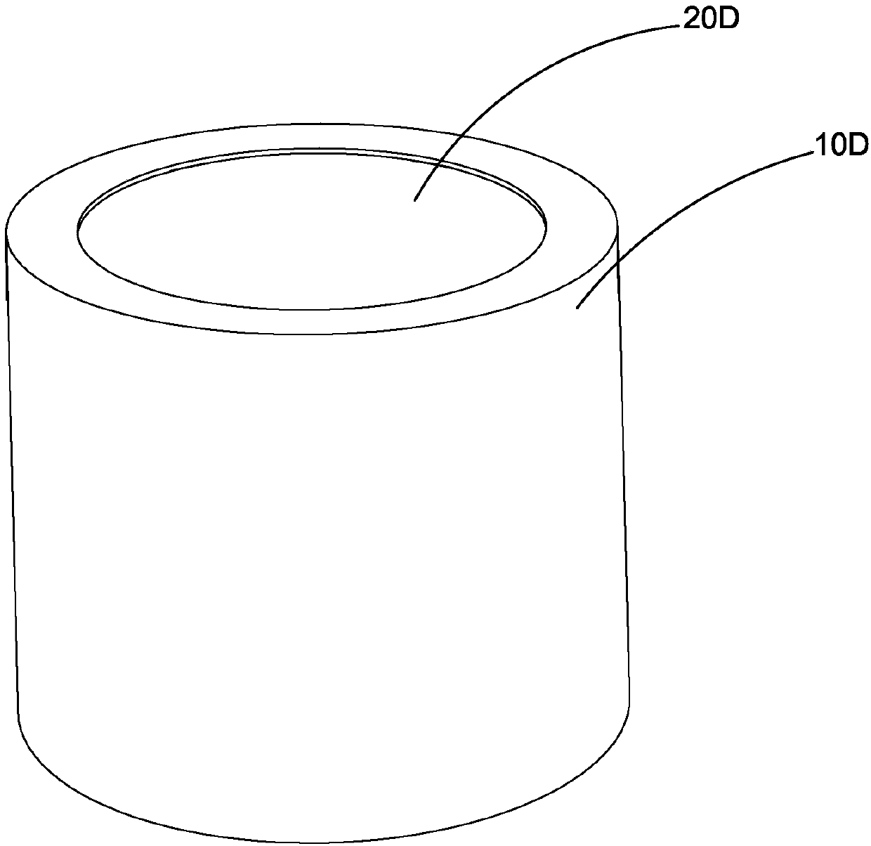
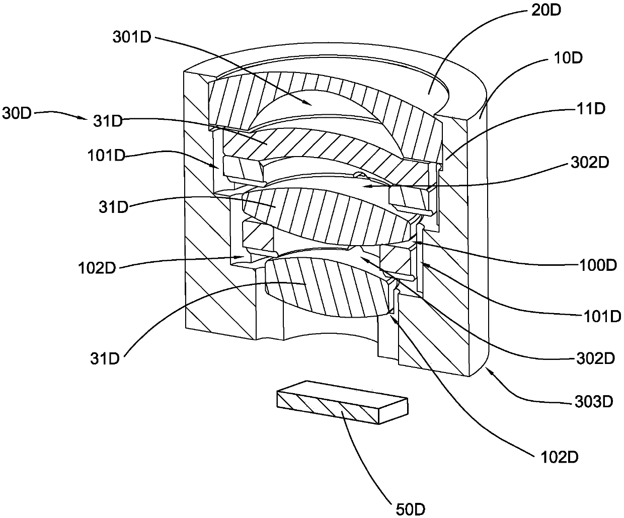
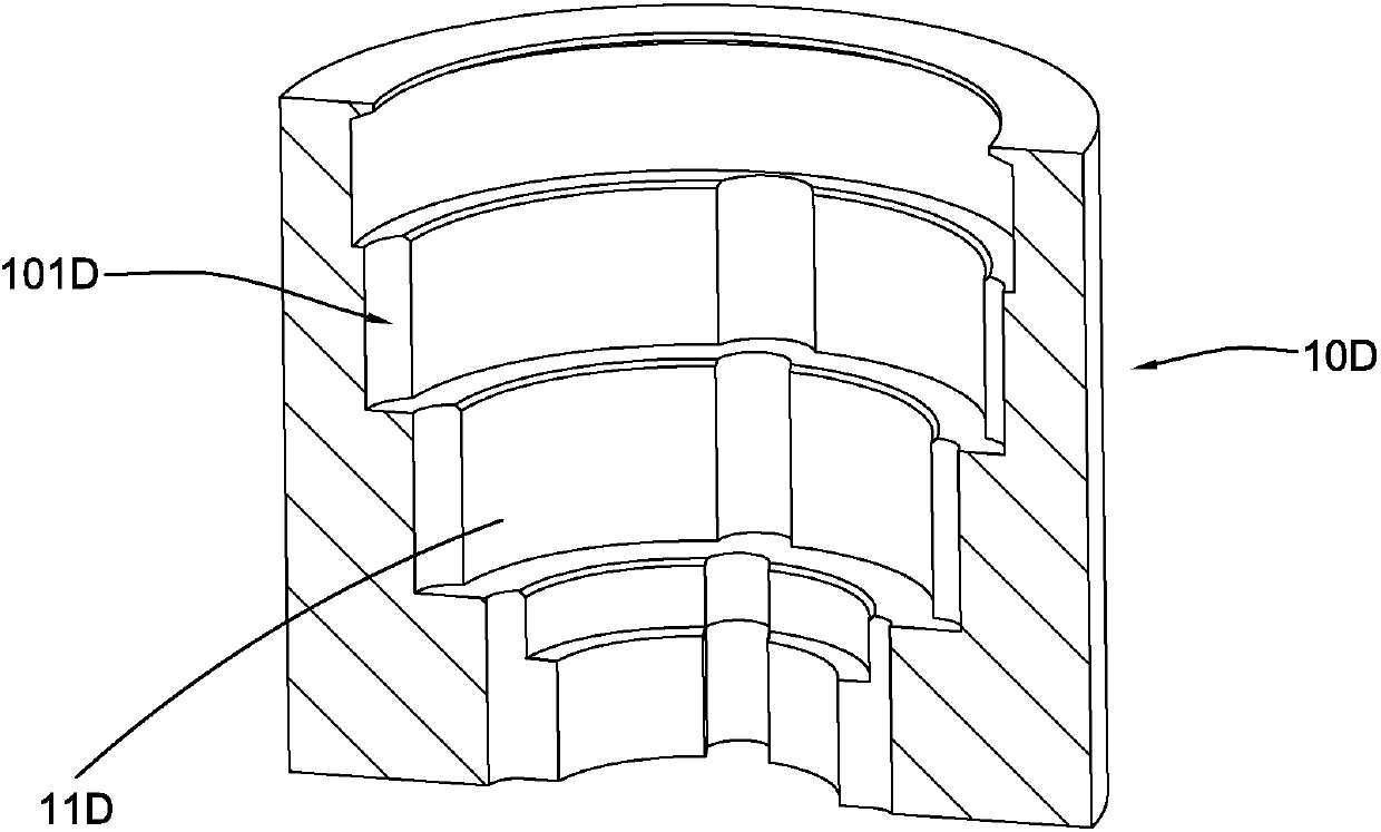
[0046] With reference to the accompanying drawings of the present invention figure 1 with Figure 3B As shown, the lens according to the first preferred embodiment of the present invention is illustrated, wherein the lens includes a lens barrel 10D, a front lens 20D and a rear lens group 30D, wherein the rear lens group 30D includes at least two lenses 31D. It can be understood that the imaging light is allowed to pass through...


PUM


Abstract

The invention provides a lens used for optical imaging. The lens includes a lens barrel. An accommodation chamber is formed in the lens barrel and a front lens and a rear lens unit are disposed in theaccommodation chamber of the lens barrel. Imaging light is allowed to pass through the front lens and the rear lens unit so as to be sensed by an optical sensor arranged on the rear side of the rearlens unit. A first interval space between the front lens and the rear lens unit is defined by the front lens and the rear lens unit. One inner side wall of the lens forms at least one communication channel communicating with the first interval space, so that a heat balance channel is formed by the first interval space and the communication channel. Therefore, air convection in the first interval space is achieved through the heat balance channel.

Description

technical field [0001] The invention relates to a lens, in particular to a lens capable of rapidly realizing heat balance in each space inside the lens when the temperature of the external environment or the temperature inside the lens changes. In other words, the lens of the present invention can quickly make the temperature of various spaces inside the lens tend to be consistent in a short time when the ambient temperature and the internal temperature of the lens change. Background technique [0002] A lens for optical imaging, such as a lens for a motor vehicle, generally includes a base, a lens barrel, and a plurality of lenses arranged in the lens barrel. There is generally an appropriate space between the lenses of the lens. When the temperature of the external environment where the lens is located changes, especially when it changes drastically, due to the heat transfer effect, the temperature of each lens of the lens will change sequentially along the direction from...

Claims


Application Information

Patent Timeline
IPC IPC(8): G02B7/02G03B30/00
CPCG02B7/028
Inventor 杨佳方利卡谢前森
Owner NINGBO SUNNY AUTOMOTIVE OPTECH
Learn More