Lattice structure and a device and method for producing same

A grid structure and grid technology, applied in the direction of structural elements, wire nets, building components, etc., can solve problems such as huge manufacturing costs, structural changes, etc.

Active Publication Date: 2018-03-27
GEOBRUGG AG
View PDF12 Cites 4 Cited by
  • Summary
  • Abstract
  • Description
  • Claims
  • Application Information

AI Technical Summary

Problems solved by technology

These welded joints, on the one hand, lead to structural changes and, on the othe

Method used


Image

  • Lattice structure and a device and method for producing same
  • Lattice structure and a device and method for producing same
  • Lattice structure and a device and method for producing same

Examples


Embodiment Construction

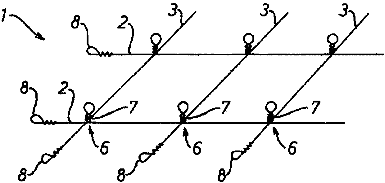
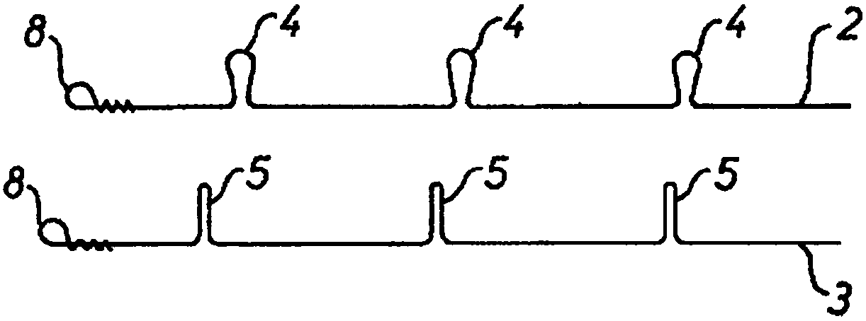
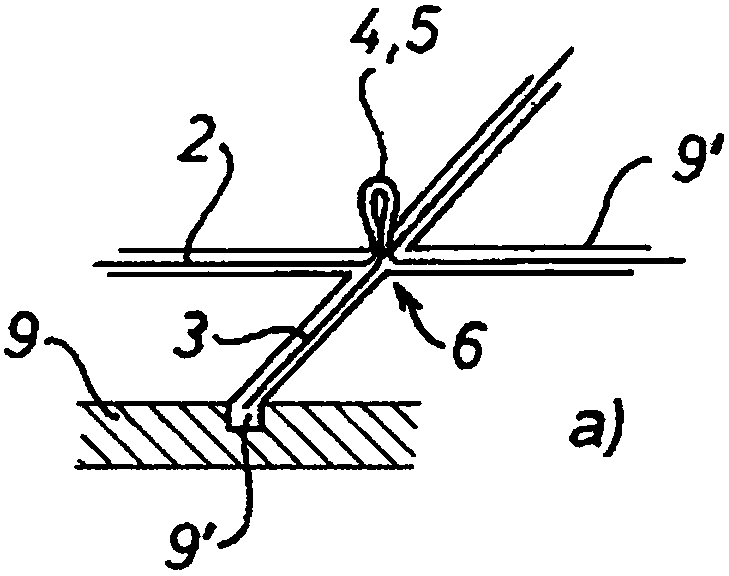
[0026] according to figure 1 The grid structure 1 to FIG. 3 consists of longitudinal elements 2 and transverse elements 3 , preferably made of steel, provided with vertically standing rings 4 and 5 . In particular, these longitudinal and transverse elements are wires, strands, ropes, rods or profiles. However, it can also be a composite product comprising steel and synthetic material and / or synthetic product and also a sandwich element thereof.

[0027] Furthermore, the transverse elements may have different dimensions and may be made of different materials and / or have different properties, eg different strength, than the longitudinal elements.

[0028] Such a grid structure 1 is suitable for various applications in the fields of reinforcement, protection and / or immobilization. Such grid structures could be embedded and / or used in concrete or asphalt for reinforcement, for example, in mining or similar applications for armor.

[0029] However, it may also be suitable for ot...


PUM


Abstract

The invention relates to a lattice structure consisting of intersecting longitudinal and transverse elements (2 and 3) such as wires, stranded wires, ropes, rods and/or profiled sections, having intersection points (6) associated therewith. These longitudinal and transverse elements (2 and 3) are interconnected by twisting at least at said intersection points (6). The connection may also be established by insertion one into another and/or by knotting. This results in a connection between the longitudinal and transverse elements which can be established without external connector means and withcomparatively low overheads.

Description

technical field [0001] The invention relates to a grid structure according to the preamble of claim 1 . Background technique [0002] Such grid structures are used as structural elements, which are implemented as flat or corrugated support grids or protective grids, where the thrust resistance of the nodes ensures that the grid is only slightly deformed even under enormous loads. To connect the wires at the junctions, soldered connections, clamps or additional wires have hitherto been used. [0003] A lattice structure of this type is disclosed in AT409506B. It consists of a bar-shaped upper and lower band, between which connecting rods have been welded in. These joint-forming welding points on the one hand lead to structural changes and on the other hand require enormous manufacturing costs when welding the strip bars together. This also applies when using machined connecting elements, which also entails high inputs with regard to labor and costs. Contents of the inven...

Claims


Application Information

Patent Timeline
IPC IPC(8): E04C5/04B21F27/02
CPCB21F27/005B21F27/02E04C5/04F16S3/08E04C5/06
Inventor 汉斯-彼得·冯·埃尔曼
Owner GEOBRUGG AG
Why Eureka
Try Eureka