Method for manufacturing heat exchanger, and heat exchanger

a technology of heat exchanger and manufacturing method, which is applied in the direction of indirect heat exchangers, light and heating apparatus, laminated elements, etc., can solve the problems of increasing material cost, increasing the thickness of plating film, and affecting the performance of heat exchangers, etc., to achieve high corrosion resistance, increase material cost, and secure corrosion resistance

Inactive Publication Date: 2018-05-01
DENSO CORP
View PDF30 Cites 1 Cited by
  • Summary
  • Abstract
  • Description
  • Claims
  • Application Information

AI Technical Summary

Benefits of technology

[0005]It is necessary to secure corrosion resistance with respect to condensed water for the exhaust gas heat exchanger. Consequently, a material with high corrosion resistance (for example, a stainless steel containing chromium at the maximum) is used as the material of components of the exhaust gas heat exchanger. Thus, the material cost increases.
[0008]An object of the disclosure is to provide a method for manufacturing a heat exchanger and a heat exchanger such that the occurrence of a through hole due to corrosion (pitting) can be reliably restricted.
[0010]Accordingly, the occurrence of a through hole due to corrosion in the heat exchanger components can be restricted by the film being formed on the surfaces of the heat exchanger components. As the film formation step is carried out after the assembly step, the film can be prevented from being damaged when conveying the components or when assembling the components. Furthermore, by the film being formed on the surfaces of the heat exchanger components using a chemical vapor deposition method, which is one kind of dry coating method, a minute portion inside the heat exchanger can be prevented from being blocked and clogged when carrying out the film formation step. Consequently, the occurrence of a through hole due to corrosion in the heat exchanger components can be reliably restricted.
[0012]Accordingly, the film can be prevented from melting when brazing, because the film formation step is carried out after the brazing step. Thus, the film can be more reliably formed on the surfaces of the heat exchanger components.

Problems solved by technology

Thus, the material cost increases.
However, the plating process causes the thickness of the plating film to be large.
Further, when performing a plating process on a heat exchanger structure including components such as the tube and the inner fin, there is concern that minute portions (for example, the inner fin) inside the heat exchanger structure may be blocked, because the plating film is formed using a liquid-state metal.
Because of this, employing this method is difficult.
However, there is a possibility of the plating film being damaged when conveying the components or when assembling the components, so employing this method is also difficult.

Method used


Image

  • Method for manufacturing heat exchanger, and heat exchanger
  • Method for manufacturing heat exchanger, and heat exchanger
  • Method for manufacturing heat exchanger, and heat exchanger

Examples


first embodiment

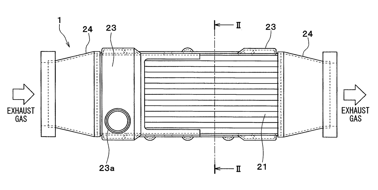
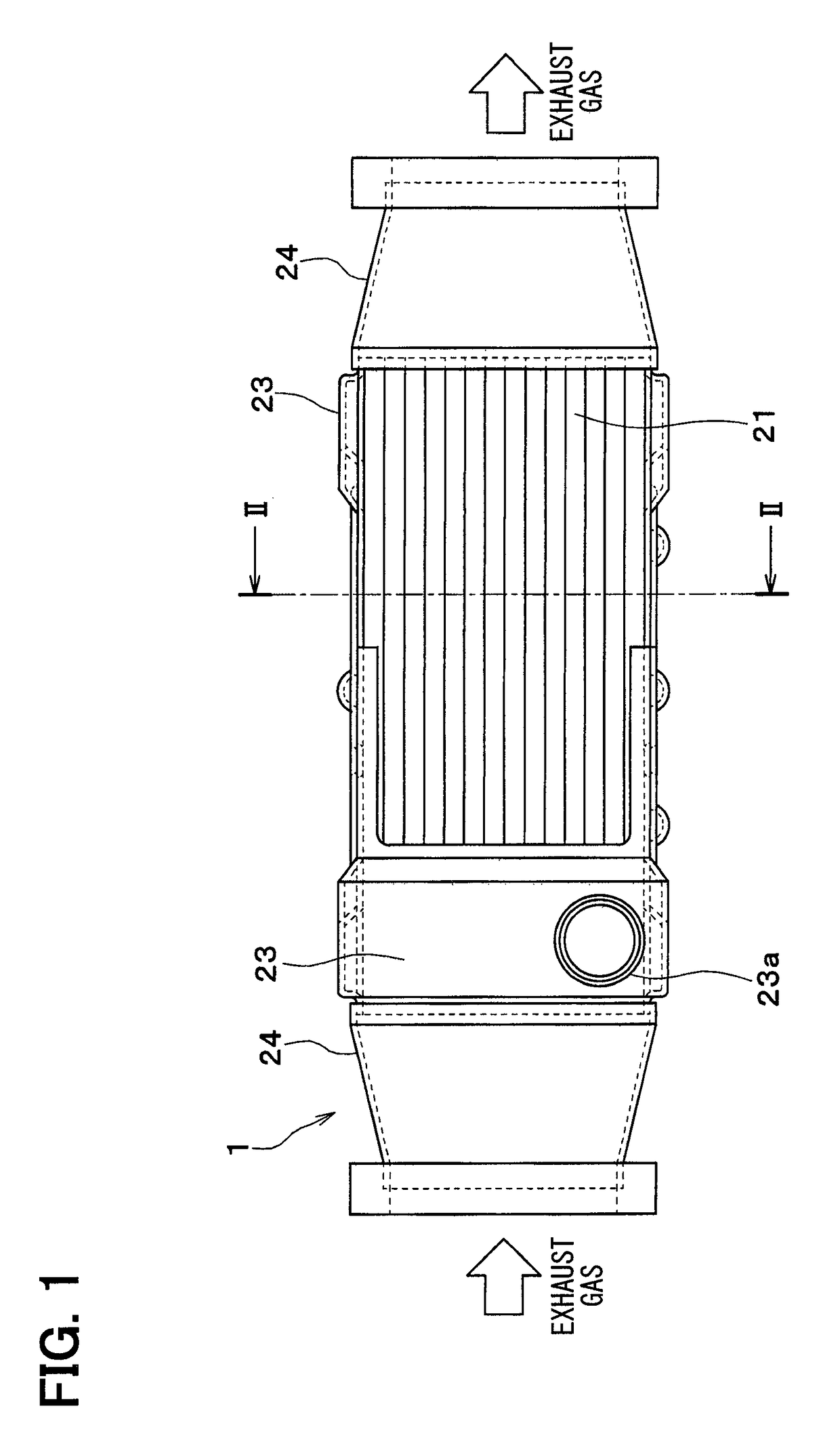
[0028]A first embodiment is described with reference to FIGS. 1-5. In the present embodiment, a heat exchanger according to the present disclosure is applied to an exhaust heat exchanger (EGR cooler).

[0029]An EGR cooler 1 is an exhaust gas heat exchanger. When exhaust gas generated by combustion in a non-illustrated internal combustion engine (engine) is recirculated to the engine, the exhaust gas is cooled by a cooling water (cooling medium) of the engine. As shown in FIGS. 1-3, the EGR cooler 1 includes plural tubes 21, an inner fin 22, a water tank 23, and an exhaust tank 24. These members 21 to 24 are made of an aluminum alloy, and are joined by brazing.

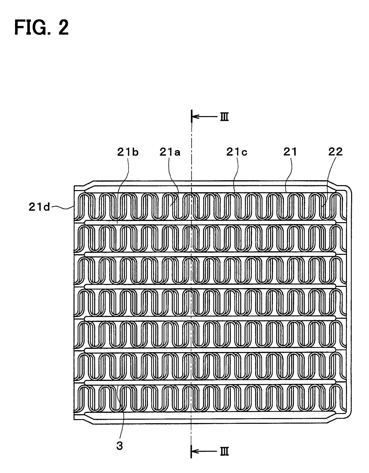
[0030]As shown in FIG. 2 and FIG. 3, the tube 21 is a pipe configuring an exhaust path 21a along which exhaust gas flows, and the exhaust gas flows through the interior of the tube 21. Cooling water flows along the exterior of the tube 21, and the exhaust gas and the cooling water are caused to exchange heat via the tube 21.

[0031...

second embodiment

[0048]A second embodiment of the disclosure will be described, based on FIG. 6. In the second embodiment, a film 30 formed on the surface of a core member 20 of a tube 21 and an inner fin 22 has a potential less noble than that of the core member 20. In this embodiment, the film 30 is made of Al2O3.

[0049]Because of this, the corrosion resistance of the core member 20 is relatively high with respect to the film 30. Therefore, the film 30 performs a sacrificial corrosion action with respect to the core member 20, such that the core member 20 can be prevented from corroding.

[0050]As shown in FIG. 6, even in a case where a through hole is generated in the film 30 by corrosion due to an adhesion of condensed water, corrosion of the film 30 advances in a direction (the arrow directions in FIG. 6) parallel to the plate surface of the core member 20, such that the corrosion can be restricted from advancing in the thickness direction of the core member 20.

third embodiment

[0051]A third embodiment of the disclosure will be described, based on FIG. 7. In the third embodiment, a first corrosion-resistant film 31 and a second corrosion-resistant film 32 having potentials more noble than that of the core member 20 are alternately stacked on the surface of a core member 20 of a tube 21 and an inner fin 22, as shown in FIG. 7.

[0052]Each of the first corrosion-resistant film 31 and the second corrosion-resistant film 32 is formed by atomic layer deposition. Also, the first corrosion-resistant film 31 and the second corrosion-resistant film 32 are formed in a crystalline state. In this embodiment, the first corrosion-resistant film 31 is made of TiO2, and the second corrosion-resistant film 32 is made of Cr2O3.

[0053]The occurrence of a through hole due to corrosion in the core member 20 can be reliably restricted by alternately stacking the two kinds of corrosion-resistant films 31 and 32 on the surface of the core member 20 of the tube 21 and the inner fin 2...


PUM

PropertyMeasurementUnit
thicknessaaaaaaaaaa
corrosion resistanceaaaaaaaaaa
thicknessaaaaaaaaaa

Abstract

A method for manufacturing a heat exchanger includes: assembling a plurality of heat exchanger components in an assembly step; and forming a film on surfaces of the heat exchanger components using a chemical vapor deposition method in a film formation step after the assembly step. The film can restrict a formation of a through hole due to corrosion. The film can be restricted from being damaged at a delivery or assembling time, because the film formation step is provided after the assembly step. An occurrence of clogging can be restricted at a minute portion inside of the heat exchanger in the film formation step, because the film is formed using the chemical vapor deposition method.

Description

CROSS REFERENCE TO RELATED APPLICATIONS[0001]This application is a U.S. National Phase Application under 35 U.S.C. 371 of International Application No. PCT / JP2014 / 001778 filed on Mar. 27, 2014 and published in Japanese as WO 2014 / 162700 A1 on Oct. 9, 2014. This application is based on and claims the benefit of priority from Japanese Patent Application No. 2013-077625 filed on Apr. 3, 2013. The entire disclosures of all of the above applications are incorporated herein by reference.TECHNICAL FIELD[0002]The present disclosure relates to a method for manufacturing a heat exchanger, and a heat exchanger.BACKGROUND ART[0003]An exhaust gas heat exchanger is known (for example, refer to PTL 1) in which exhaust gas is cooled by carrying out an exchange of heat between exhaust gas generated by combustion and a cooling medium. This kind of exhaust gas heat exchanger includes an inner fin joined to the inside of a tube through which exhaust gas flows, and is configured so as to cool the exhaus...

Claims


Application Information

Patent Timeline
Patent Type & Authority Patents(United States)
IPC IPC(8): B23P15/26C23C16/40F28D9/00F28D7/16F28F3/02C23C16/455
CPCB23P15/26C23C16/405C23C16/45555F28D9/0062F28F3/027F28D7/1684F28F2275/04
Inventor KAFUKU, KAZUAKIKUROYANAGI, ISAOYAMANAKA, YASUTOSHITERA, RYONOSUKESANO, YUKIHIRO
Owner DENSO CORP
Why Eureka
Try Eureka