
Integrated sensor in injection molding die, and injection molding die

A technology for injection molds and sensors, which is applied in the field of integral sensors in injection molds and injection molds, and can solve various external factors that increase signal accuracy, sensitivity, and stability, increase the complexity of signal processing calculations, and limit sensor installation positions and other issues to achieve the effect of improving accuracy and sensitivity, stability and safety, and easy assembly

Inactive Publication Date: 2018-03-30
KUNDA MOLD SHENZHEN +1
View PDF1 Cites 0 Cited by
  • Summary
  • Abstract
  • Description
  • Claims
  • Application Information

AI Technical Summary

Problems solved by technology

[0004] At this stage, the technology of shooting glass cavity with camera and ultrasonic pulse reflection method are generally used to detect the state of the melt during the injection molding process. However, in the technology of shooting glass cavity with camera, the melt needs to pass through the glass cavity instead of the traditional one. The metal mold cavity reduces the strength of the mold cavity, which seriously affects the application of this technology; in the ultrasonic pulse reflection method, the installation position of the sensor is limited, and the melt state information provided is very limited and discrete
In addition, the two important steps of signal perception and signal filtering and amplification are carried out in different individuals, which not only increases the complexity of signal processing calculations, but also increases various external factors that affect signal accuracy, sensitivity, and stability.

Method used


Image

  • Integrated sensor in injection molding die, and injection molding die
  • Integrated sensor in injection molding die, and injection molding die
  • Integrated sensor in injection molding die, and injection molding die

Examples


Embodiment 1

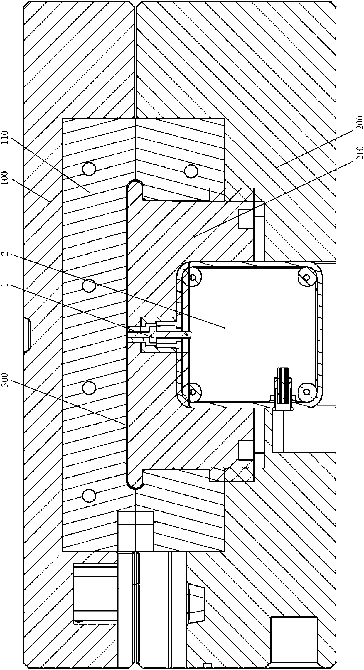
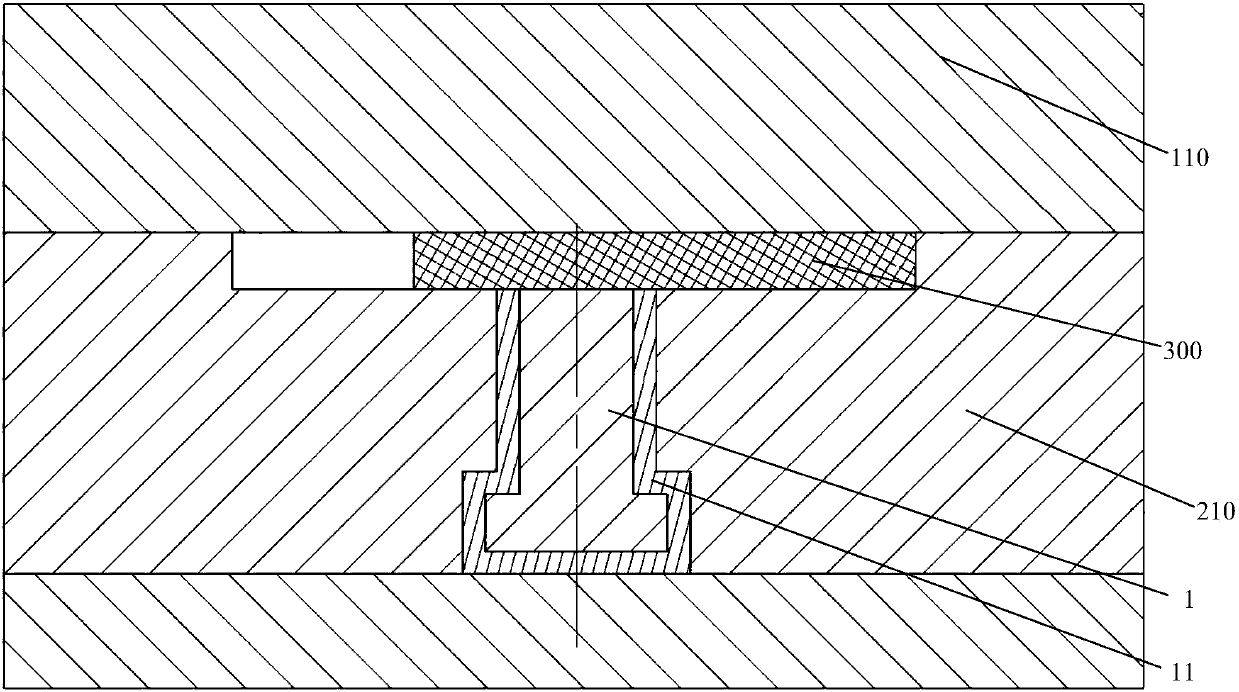
[0040] An embodiment of the present invention provides an integral sensor in an injection mold, which is suitable for an injection mold, see figure 1 , the injection mold may include: a fixed platen 100, a movable platen 200, and a cavity 300 ( figure 1 The shape of the middle cavity 300 is relatively narrow, see image 3 shape of the cavity 300).

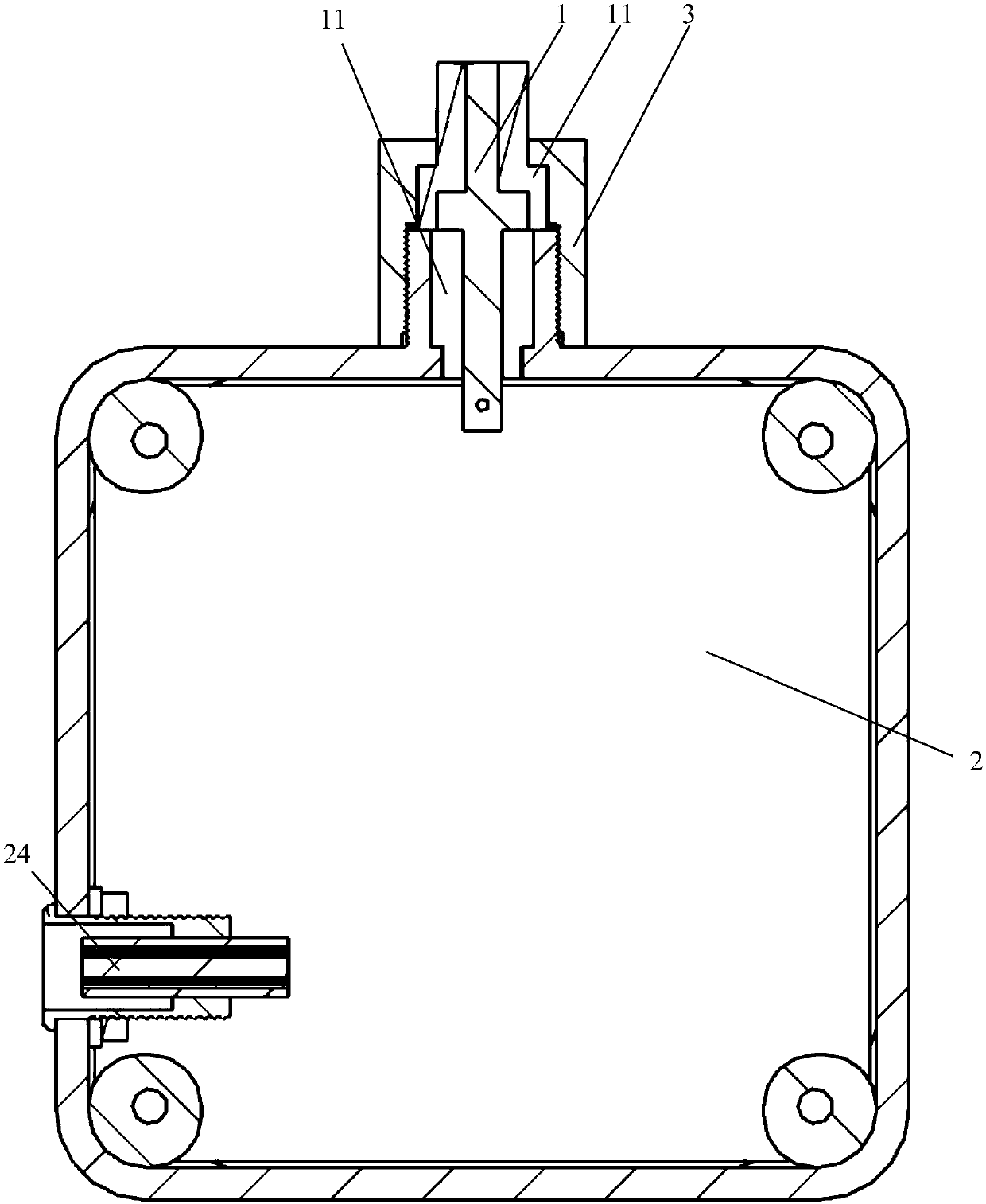
[0041] see figure 2 , the integral sensor may include: a sensor main body 1 that is arranged in the movable mold core 210 and constitutes two poles of detection capacitance with the fixed mold core 110, and is used for filtering and amplifying the capacitance signal collected by the sensor main body 1 The sensory signal is filtered to amplify box 2.

[0042] One end surface of the sensor body 1 is in contact with the mold cavity 210 , and the other end is inserted into the sensing signal filter amplification box 2 . The sensor body 1 is surrounded by an insulating layer 11 which is insulated from the outside.

[0043]In this e...

Embodiment 2

[0067] An embodiment of the present invention provides an injection mold equipped with the integral sensor described in Embodiment 1, see Figure 6 , the injection mold can include:

[0068] The fixed platen 100 , the movable platen 200 , the mold cavity 300 for forming a product between the fixed mold core 110 of the fixed platen 100 and the movable mold core 210 of the movable platen 200 , and an integral sensor 400 .

[0069] The integral sensor 400 may include: a sensor main body 1 that runs through the movable mold core 210 and forms two poles of detection capacitance with the fixed mold core 110, and a sensor body 1 for filtering and amplifying the capacitance signal collected by the sensor main body 1. Sensing signal filtering amplification box 2,

[0070] One end surface of the sensor body 1 is in contact with the cavity 210 , and the other end is inserted into the sensing signal filter amplification box 2 , and an insulating layer is provided around the sensor body 1...


PUM

PropertyMeasurementUnit
Diameteraaaaaaaaaa
Lengthaaaaaaaaaa

Abstract

The invention discloses an integrated sensor in an injection molding die, and the injection molding die. The integrated sensor in the injection molding die comprises: a sensor main body (1) penetrating through a movable die core and forming two electrodes of a detection capacitor together with a fixed die core, and a sensing signal filtering and amplifying box (2) used for filtering and amplifyinga capacitance signal acquired by the sensor main body (1). The integrated sensor can obtain the state of a melt in a die cavity according to the change of the capacitance signal of the detection capacitor in different stages in the whole injection molding process, the detected melt state information is continuous and abundant, and the sensor main body and the sensing signal filtering and amplifying box are integrated to make the capacitance signal directly input to the sensing signal filtering and amplifying box in a zero distance manner from the sensor main body, so the precision, the sensitivity and the stability of the sensing signal of the integrated sensor are improved, and the service life of the integrated sensor is prolonged.

Description

technical field [0001] The invention relates to the technical field of injection molds, in particular to an integral sensor in an injection mold and an injection mold. Background technique [0002] With the sublimation of fierce competition in the product market, advocating high efficiency, energy saving, environmental protection, and low cost has become the magic weapon and foundation for enterprises to win in the competition. One of the key links is the efficiency and quality monitoring of the production process of injection molding products. High intelligence of control and control, low cost expenditure, effective resource utilization and other aspects put forward higher, more competitive, smarter and more automated requirements. [0003] During the entire injection molding process, the state of the melt in the cavity changes greatly, and these changes have a decisive impact on the quality of the product. Therefore, the detection of the melt state, especially the detecti...

Claims


Application Information

Patent Timeline
IPC IPC(8): B29C45/26B29C45/76G01D5/12
CPCB29C45/26B29C45/76G01D5/12B29C45/2602B29C2945/7615B29C2945/76257B29C2945/76381B29C2945/76454
Inventor 尹运文汪智勇姜芝君杨毅莫胜勇高福荣
Owner KUNDA MOLD SHENZHEN
Learn More