Composite insulating cross arm

A composite insulation and cross-arm technology, which is applied in the field of composite insulation cross-arm, can solve the problems of many dangerous points, complicated installation process, and high labor intensity, and achieve the goals of improving safety performance and service life, simplifying the installation process, and reducing labor intensity. Effect

Active Publication Date: 2018-03-30
方隆集团有限公司
View PDF11 Cites 2 Cited by
  • Summary
  • Abstract
  • Description
  • Claims
  • Application Information

AI Technical Summary

Problems solved by technology

[0002] According to the research results, the lightning flashover depends on the overvoltage value and the line insulation level. The research shows that the severity of the arc caused by the lightning strike decreases with the decrease of the electric field gradient along the flashover path; so improving the line insulation level and increasing the power The insulation performance of the pole tower can significantly improve the lightning flashover; at present, most power pole towers in domestic and foreign distribution network systems have iron cross arms, wooden cross arms, and porcelain cross arms; the wooden cross arms are not strong enough and have weak corrosion resistance; Porcelain cross-a

Method used


Image

  • Composite insulating cross arm
  • Composite insulating cross arm
  • Composite insulating cross arm

Examples


Embodiment 1

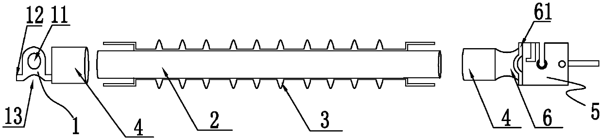
[0031] see figure 1 As shown, the present invention provides a composite insulating cross arm, comprising a mandrel 2, the mandrel 2 is a cylindrical structure, the outer surface of the mandrel 2 is provided with a rubber sheath 3; the two ends of the mandrel 2 are provided with There is a crimped cylinder clamp 4; one end of the cylinder clamp 4 is provided with a cavity that is matched with the mandrel 2, and the other end of the cylinder clamp 4 is closed; one of the cylinder clamps 4 is closed The side wall of the end is provided with a first connecting fitting 1 which is fixedly connected with it. The middle part of the first connecting fitting 1 is provided with an elliptical through hole 11, and the middle part of the top is provided with an arc-shaped groove 13; both sides of the top are provided with lugs 12, wherein The side wall of one lug 12 is fixedly connected to the cylindrical fixture 4; the closed end side wall of the other cylindrical fixture 4 is fixedly con...

Embodiment 2

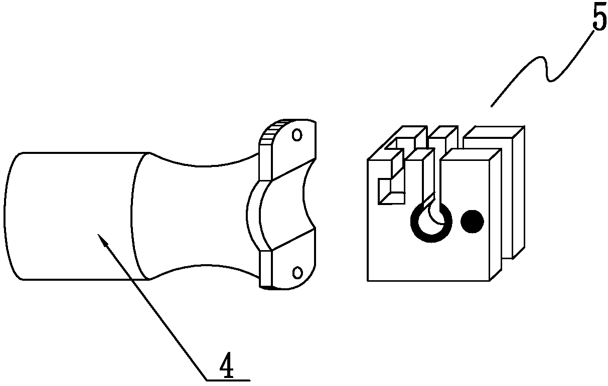
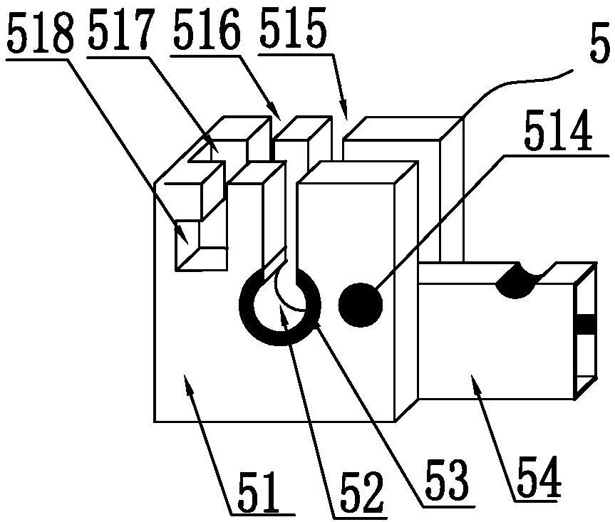
[0034] see figure 2 with image 3 As shown, as a technical optimization solution of the present invention, the lock assembly 5 includes a side plate 51 fixedly connected with the second connecting hardware 6; the middle part of the side plate 51 is provided with an arc-shaped wire hole running through the front and rear surfaces 52; the opening of the arc-shaped line hole 52 is upward; the opening of the arc-shaped line hole 52 is provided with a first vertical groove 515 penetrating to the top of the side plate 51; the side plate 51 is close to the cylinder clamp 4 One end of the first vertical groove 515 is also provided with a second vertical groove 516 parallel to the first vertical groove 515; the bottom of the second vertical groove 516 extends toward the direction of the cylinder clamp 4 to pass through the front and rear surfaces of the side plate 51 and is in line with the The card slot 518 connected with the second vertical groove 516; the middle part of the side p...

Embodiment 3

[0037] see Figure 4 As shown, as a technical optimization solution of the present invention, the top of the rotating clamping plate 54 is provided with a crimping groove 513 matching the arc-shaped wire hole 52; A first cavity 520 is opened, and a connecting seat 58 is slidably connected inside the first cavity 520; a fixing plate 510 is provided on the outside of the connecting seat 58; The slot 518 matches the block 511; the bottom of the fixing plate 510 is provided with a push-pull assembly; the crimping slot is for fixing the wire.

[0038] When in use, put the wires directly from the top of the first vertical slot into the arc-shaped slot, then hold the push-pull assembly and turn the fixing plate into the horizontal slot to press the crimping slot on the wires in the arc-shaped slot, and then Push the push-pull assembly, the fixed plate moves to the direction of the card slot, and drives the connecting seat to move to the direction of the card slot. At this time, the ...


PUM


Abstract

The invention discloses a composite insulating cross arm comprising a mandrel. The mandrel is of a cylindrical structure, and a rubber sheath is arranged on the outer surface of the mandrel. The two ends of the mandrel are provided with cylinder clamps connected in a pressed mode. One ends of the cylinder clamps are provided with cavities which are connected with the mandrel in matched and sleevedmodes, and the other ends of the cylinder clamps are closed. The side wall of the closed end of one of the cylinder clamps is provided with a first connecting fitting fixedly connected with the cylinder clamp, an oval through hole is formed in the middle of the first connecting fitting, an arc-shaped groove is formed in the middle of the top end of the first connecting fitting, convex lugs are arranged on the two sides of the top of the first connecting fitting, and the side wall of one of the convex lugs is fixedly connected with the corresponding cylinder clamp. The side wall of the closedend of the other cylinder clamp is fixedly connected with one end of a second connecting fitting which is overall in an sunken arc-shaped cylinder shape, the other end of the second connecting fittingis provided with symmetrical arc-shaped convex lugs, and the side wall of the second connecting fitting is provided with a locking assembly fixedly connected with the second connecting fitting.

Description

technical field [0001] The invention belongs to the field of power grid equipment; in particular, it relates to a composite insulating cross arm. Background technique [0002] According to the research results, the lightning flashover depends on the overvoltage value and the line insulation level. The research shows that the severity of the arc caused by the lightning strike decreases with the decrease of the electric field gradient along the flashover path; so improving the line insulation level and increasing the power The insulation performance of the pole tower can significantly improve the lightning flashover; at present, most power pole towers in domestic and foreign distribution network systems have iron cross arms, wooden cross arms, and porcelain cross arms; the wooden cross arms are not strong enough and have weak corrosion resistance; Porcelain cross-arms are not strong enough and have insufficient bending resistance; iron cross-arms have poor insulation performan...

Claims


Application Information

Patent Timeline
IPC IPC(8): E04H12/24
CPCE04H12/24
Inventor 杨帆任红兴杨刻杨晴
Owner 方隆集团有限公司
Why Eureka
Try Eureka