
Projection lamp simulating sky effect

A technology for simulating the sky and projecting lights, which is applied in the field of projecting lights, can solve the problems of rigid patterns or patterns, and cannot reproduce realistic simulations, so as to achieve the effect of improving the degree of realism

Pending Publication Date: 2018-03-30
SHENZHEN QIAOHUA IND
View PDF0 Cites 16 Cited by
  • Summary
  • Abstract
  • Description
  • Claims
  • Application Information

AI Technical Summary

Problems solved by technology

However, the patterns or patterns projected by the existing pattern projection lamps are usually relatively blunt. Natural phenomena such as the sky cannot be realistically simulated and reproduced indoors by pattern projection lamps. This is a pity for the general public who do not have a 360° panorama room.

Method used


Image

  • Projection lamp simulating sky effect
  • Projection lamp simulating sky effect
  • Projection lamp simulating sky effect

Examples


Embodiment 1

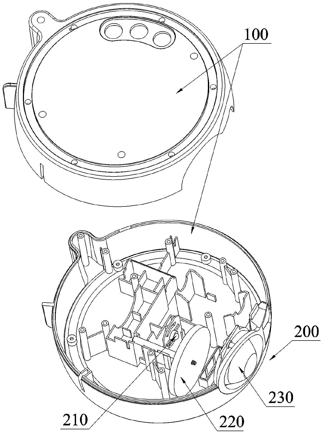
[0032] Such as figure 1 As shown, a projection lamp for simulating sky effects includes a casing 100 and a first light-emitting assembly 200 disposed in the casing 100 . The first light-emitting component 200 includes a first light source 210 that generates a first light, a first frosted glass 220 and a convex lens 230 that are arranged on the light path of the first light, and the three are sequentially arranged in the casing 100, and the first The first light emitted by a light source 210 is projected onto a surface through the first ground glass 220 and the convex lens 230 to present a cloud effect.

Embodiment 2

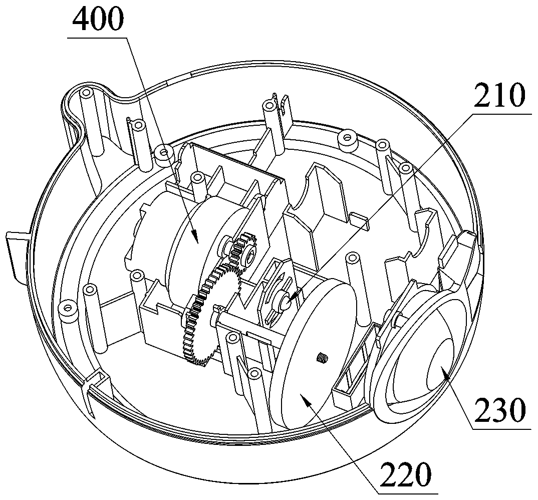
[0034] The difference between this embodiment and embodiment 1 is that, as figure 2 As shown, the projection lamp for simulating the sky effect also includes a driving device 400, the first frosted glass 220 is in transmission connection with the driving device 400, and when the first frosted glass 220 moves under the control of the driving device 400, the first light source 210 emits The first light rays pass through the first frosted glass 220 and the convex lens 230 and are projected onto a surface to present changing cloud effects. The first frosted glass 220 rotates under the drive of the driving device 400. Due to the irregularity of the surface folds of the first frosted glass 220, the cloud effect that the first light passes through the first frosted glass 220 and is projected on a surface presents irregular movement and irregular motion. Regular shape changes further improve the fidelity of the simulated sky effect.

Embodiment 3

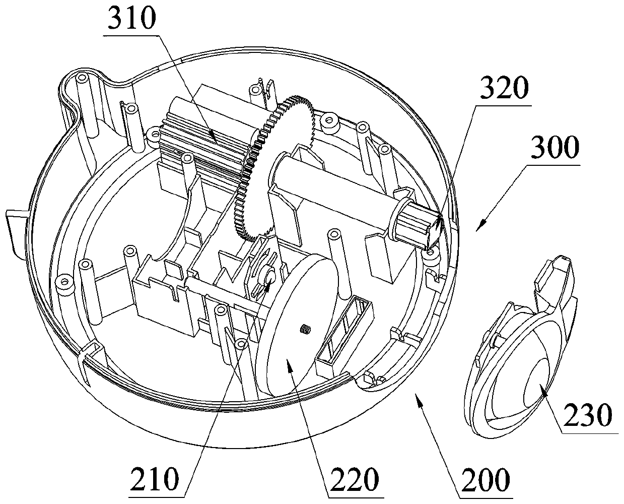
[0036] The difference between this embodiment and embodiment 1 is that, as image 3 As shown, the projection lamp for simulating the sky effect also includes a second light-emitting assembly 300, and the second light-emitting assembly 300 includes a second light source 310 for generating a second light and a grating sheet arranged on the light path of the second light 320. The second light emitted by the second light source 310 is projected onto a surface through the grating sheet 320 to present a star effect. The second light passes through the grating sheet 320 and presents dotted star-like patterns on a surface, thereby realizing a realistic starry sky indoors.


PUM


Abstract

The invention relates to the field of projection lamps, and discloses a projection lamp simulating the sky effect. The projection lamp comprises a first light emitting assembly. The first light emitting assembly comprises a first light source for generating first light, first ground glass arranged on a light path of the first light and a convex lens, wherein the first light source, the ground glass and the convex lens are arranged in sequence. The first light emitted by the first light source penetrates the first ground glass and the convex lens to be projected to a surface to show the cloud effect. According to the projection lamp, the first ground glass is arranged between the first light source and the convex lens, the first light emitted by the first light source penetrates the first ground glass and the convex lens and then shows the cloud effect in a shape similar to a cotton ball on the surface, and therefore the aim of creating the sky effect indoors is achieved.

Description

technical field [0001] This patent relates to the field of projection lamps, more specifically, to a projection lamp for simulating sky effects. Background technique [0002] Lighting is an important means to decorate and beautify the environment and create an artistic atmosphere. In order to decorate the interior space, increase the spatial level, and render the atmosphere of the environment, it is very important to use decorative lighting and decorative lamps. In the environmental design of modern home buildings, film and television buildings, commercial buildings and entertainment buildings, lighting has become a part of the whole. Lamps not only play a role in ensuring lighting, but also pay attention to their shapes, materials, colors, proportions, and scales. Lamps have become indispensable decorations for indoor spaces. Lighting designers give full play to the brilliance and color of lights through rhythmic control of light and shade, looming, circumflex, and streng...

Claims


Application Information

Patent Timeline
IPC IPC(8): F21S10/00F21V19/00F21V13/00F21V14/00F21V23/00F21V23/04F21V5/04F21W121/00
CPCF21S10/00F21V5/04F21V13/00F21V14/00F21V19/00F21V23/003F21V23/04F21W2121/008F21S10/007F21V5/048F21V9/02F21V11/06F21V13/02
Inventor 杨瑞士
Owner SHENZHEN QIAOHUA IND
Learn More