
A small laser receiving device in a strong magnetic field environment

A technology of laser receiving and strong magnetic field, applied in the field of laser detection, can solve the problems of being susceptible to electromagnetic environment interference, occupying a large space, and complicated structure of a large field of view angle mirror, so as to achieve anti-interference ability, small occupation space and simple assembly. Effect

Active Publication Date: 2019-06-21
NANJING UNIV OF SCI & TECH
View PDF6 Cites 0 Cited by
  • Summary
  • Abstract
  • Description
  • Claims
  • Application Information

AI Technical Summary

Problems solved by technology

[0004] The technical problem solved by the present invention is to provide a small laser receiving device in a strong magnetic field environment, so as to solve the problems that the large field of view mirror has a complex structure, occupies a large space and is easily disturbed by the electromagnetic environment

Method used


Image

  • A small laser receiving device in a strong magnetic field environment
  • A small laser receiving device in a strong magnetic field environment
  • A small laser receiving device in a strong magnetic field environment

Examples


Embodiment Construction

[0017] In order to illustrate the technical solution and technical purpose of the present invention, the present invention will be further introduced below with reference to the accompanying drawings and specific embodiments.

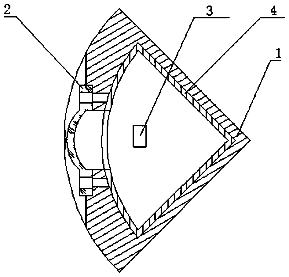
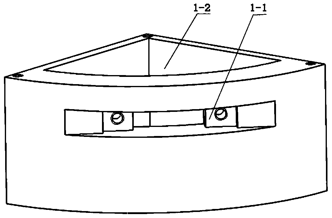
[0018] combine figure 1 , figure 2 , a small laser receiving device in a strong magnetic field environment of the present invention, comprising a mounting seat 1, a receiving objective lens 2, and a receiving circuit 3;

[0019] The mounting seat 1 is a 90° sector structure, the fan-shaped arc end of the mounting seat 1 is provided with a mounting groove 1-1, the receiving objective lens 2 is fixedly connected in the mounting groove 1-1, and the entire receiving objective lens 2 is located in the mounting groove 1-1. 1, and the width of the installation groove 1-1 is larger than the receiving range of the optical path of the receiving objective lens 2, which can not only ensure that the optical path is not blocked, but also protect the receiving objec...


PUM


Abstract

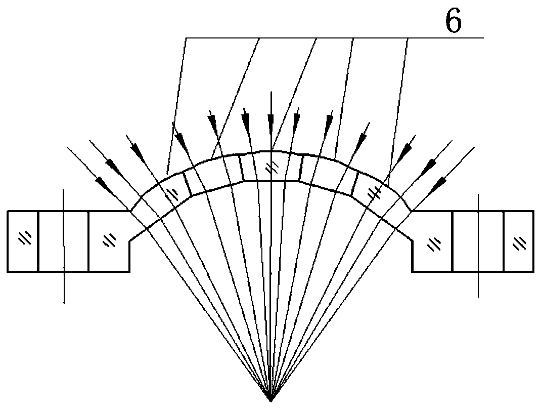
The invention discloses a small laser receiving device under a strong magnetic environment, which includes a mounting base, a receiving objective lens and a receiving circuit. The mounting base is ofa 90-degree sector structure, and is provided with a mounting slot at the sector arc end thereof. The receiving objective lens is fixedly connected into the mounting slot, and the width of the mounting slot is larger than the receiving scope of the light path of the receiving objective lens. The mounting base is internally provided with a mounting cavity. The receiving circuit is arranged in the mounting cavity, and is used for converting an optical signal received by the receiving objective lens into an electrical signal. The arch structure in the middle of the receiving objective lens is composed of multiple sections of spherical mirrors lapped one on another. The outer surface of the lens of each section of spherical mirror is a Tschelning ellipse, and the inner surface is a planar square. A shielding sleeve is also arranged in the mounting cavity. The laser receiving device of the invention is small, costs low, and has a simple structure. The laser receiving device is resistant tointerference in a strong magnetic environment. It is ensured that a laser detection system can work normally in a strong magnetic environment.

Description

technical field [0001] The invention mainly relates to the field of laser detection, in particular to a small laser receiving device in a strong magnetic field environment. Background technique [0002] With the development of science and technology, laser detection technology has been widely used in various fields such as military and civilian use, and has played an important role in promoting the development of technical fields such as surveying and mapping, communication, target detection and identification, and guidance. [0003] As the electromagnetic interference sources in the application environment become more and more complex and the electronic equipment becomes more and more sophisticated, especially the interference of the strong electromagnetic environment on the optoelectronic equipment becomes more and more serious, which can easily lead to the failure of the laser detection system. When laser detection technology is used in target search, azimuth recognition ...

Claims


Application Information

Patent Timeline
Patent Type & Authority Patents(China)
IPC IPC(8): G02B6/42
CPCG02B6/4277G02B6/4296
Inventor 沈娜张祥金吴若愚姚宗辰戴炜张合何勇冯涛
Owner NANJING UNIV OF SCI & TECH
Learn More