Liquid crystal display device

A liquid crystal display device and liquid crystal layer technology, applied in static indicators, nonlinear optics, instruments, etc., can solve problems such as panel flicker, cost increase, and system output capacity doubled

Active Publication Date: 2018-03-30
KUSN INFOVISION OPTOELECTRONICS
View PDF6 Cites 13 Cited by
  • Summary
  • Abstract
  • Description
  • Claims
  • Application Information

AI Technical Summary

Problems solved by technology

[0006] The object of the present invention is to provide a liquid crystal display device to solve the panel flicker phenomenon caused by the asymmetry of the electric field under the existing wide and narrow viewing angle panel

Method used


Image

  • Liquid crystal display device
  • Liquid crystal display device
  • Liquid crystal display device

Examples


no. 1 example

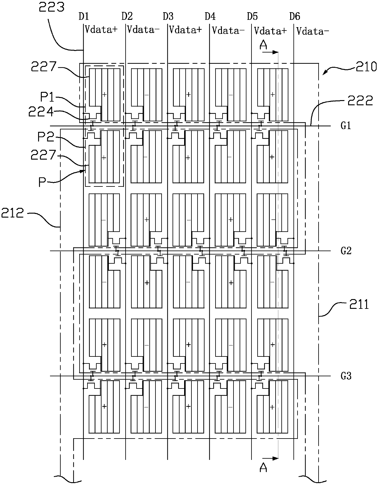
[0034] image 3 It is a schematic diagram of part of the circuit structure of the liquid crystal display device in the first embodiment of the present invention, Figure 4 It is a schematic diagram of the plane structure of the viewing angle control electrodes and the black matrix on the color filter substrate of the liquid crystal display device in the first embodiment of the present invention, Figure 5 for image 3 Schematic cross-section along the A-A line in , please refer to image 3 As shown in FIG. 4 , the liquid crystal display device includes a color filter substrate 21 , an array substrate 22 disposed opposite to the color filter substrate 21 , and a liquid crystal layer 23 located between the color filter substrate 21 and the array substrate 22 .

[0035] The liquid crystal display device provided in this embodiment is suitable for liquid crystal display devices of In-Plane Switching (IPS), Fringe Field Switching (FFS) and other modes, and the common electrode and...

no. 2 example

[0063] Figure 9 The waveform diagrams of the first AC control voltage applied to the first electrode portion and the second AC control voltage applied to the second electrode portion in the second embodiment of the present invention, please refer to Figure 9 , the voltage output to the common electrode 225 is the DC common voltage 30 (ie DCVcom) when the liquid crystal display device is displayed (whether under a wide viewing angle or a narrow viewing angle). The difference between this embodiment and the first embodiment is that, when an AC voltage is applied to the viewing angle control electrode 210 , a periodic first AC control voltage 31 is respectively applied to the first electrode portion 211 and the second electrode portion 212 , respectively. (ie com1) and the second AC control voltage 32 (ie com2), and the potential difference between the first AC control voltage 31 and the second AC control voltage 32 and the DC common voltage 30 is equal.

[0064] Specifically ...

no. 3 example

[0070] Figure 10 It is a schematic diagram of the partial circuit structure of the liquid crystal display device in the third embodiment of the present invention, please refer to Figure 10 The difference between this embodiment and the above-mentioned first embodiment is that, in this embodiment, a pixel electrode 227 is arranged in each pixel unit P, and the pixel electrode 227 is arranged in the first sub-pixel P1 and the second sub-pixel P1 at the same time. The pixel P2 is electrically connected to the scan line 222 and the data line 223 in the pixel unit P through a thin film transistor 224 . For the rest of the content of this embodiment, reference may be made to the description of the first embodiment above, and details are not repeated here.


PUM


Abstract

The invention provides a liquid crystal display device. Each pixel unit on an array substrate comprises a first sub-pixel and a second sub-pixel; a visual angle control electrode on a colored film substrate comprises a first electrode part and a second electrode part which are insulated from each other; the first electrode part correspondingly covers one of the first sub-pixel and the second sub-pixel of each pixel unit; the second electrode part correspondingly covers the other one of the first sub-pixel and the second sub-pixel of each pixel unit; and a first alternating-current control voltage and a second alternating-current control voltage are separately applied to the first electrode part and the second electrode part, the polarity of the first alternating-current control voltage isopposite to the polarity of the second alternating-current control voltage, and the potential difference between the first electrode part and a common electrode and the potential difference between the second electrode part and the common electrode are equal or the equivalent potential difference between the first electrode part in two frames of pictures in a period and the common electrode and the equivalent potential difference between the second electrode part in the two frames of pictures in the period are equal. According to the driving framework, by complementarity and phase difference of the two alternating-current voltages, bright difference is generated between the two sub-pixels in each pixel unit to carry out brightness compensation, and thus, the problem of flashing of a panelis solved.

Description

technical field [0001] The present invention relates to the technical field of liquid crystal display, in particular to a liquid crystal display device. Background technique [0002] Liquid crystal display (LCD) has the advantages of good picture quality, small size, light weight, low driving voltage, low power consumption, no radiation and relatively low manufacturing cost, and is dominant in the field of flat panel display. [0003] Now, liquid crystal display devices are gradually developing towards a wide viewing angle. For example, a liquid crystal display device using an in-plane switching mode (IPS) or a fringe field switching mode (FFS) can achieve a wider viewing angle. The wide viewing angle design allows users to see a complete and undistorted picture from all directions. However, in today's society, people pay more and more attention to protecting their privacy, and there are many things they don't like to share with others. In public places, I always want to k...

Claims


Application Information

Patent Timeline
IPC IPC(8): G02F1/13G02F1/133G02F1/1343G02F1/137
CPCG02F1/1323G02F1/13306G02F1/134309G02F1/137
Inventor 钟德镇苏子芳姜丽梅
Owner KUSN INFOVISION OPTOELECTRONICS
Why Eureka
Try Eureka