Submergible carrier

A vehicle and platform technology, applied in special-purpose ships, ships, motor vehicles, etc., can solve the problems of being attacked, equipment loss, etc., and achieve the effect of easy management, reducing complexity and cost

Inactive Publication Date: 2018-04-03
王宜
View PDF7 Cites 18 Cited by
  • Summary
  • Abstract
  • Description
  • Claims
  • Application Information

AI Technical Summary

Problems solved by technology

[0016] The present invention mainly solves the problem that traditional amphibious transport ships transport landing combat equipment, especially main battle tank equipment, which are easy to be detected and attacked during the voyage and transfer process, and the centralized loading method is easy to cause the carried equipment to be damaged. The problem of large losses, to solve the above problems, the vehicle for transporting landing combat equipment must meet the following four technical conditions:

Method used


Image

  • Submergible carrier
  • Submergible carrier
  • Submergible carrier

Examples


Embodiment 1

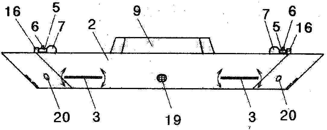
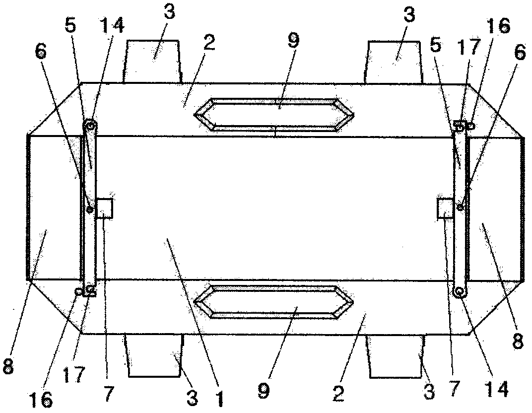
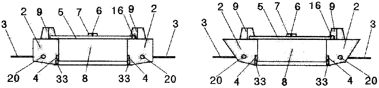
[0075] Embodiment 1: The submersible vehicle is characterized in that the cabin body 2 is on both sides of the bearing platform 1, the cabin body 2 is connected through the bearing platform 1 at the lower part or bottom, and the airfoil 3 is on the outside of the cabin body 2 , a general structure of which is Figure 1A to Figure 1D As shown, the cabins 2 on both sides of the vehicle and the bearing platform 1 in the middle are both front and rear symmetrical structures so that they have the same navigation capability. The shell of the cabin 2 and the surface of the bearing platform are made of steel or aluminum alloy materials, and the truss keel is Made of high-strength steel or aluminum alloy, the front and rear ends of the cabin are wedge-shaped or streamlined to reduce navigation resistance, but the top and the inner bulkhead are kept straight to ensure that the water flowing into the inner side and above the bearing platform is not loaded. When not being squeezed, only t...

Embodiment 2

[0099] Embodiment 2, the overall structure is the same as above, but a large-capacity battery pack is installed in the power cabin and a pure electric drive is used to drive the water pump. It is simple, but basically the distance from the towing ship to the towing ship after loading on the beach, and then from the towing ship to seizing the enemy's beach is not too far, so the capacity of the battery pack is sufficient to support the required power. One advantage of this solution is that it is pure Electric propulsion does not need to provide air to the engine and set up a snorkel, so it is more suitable to use a higher-power electric main engine to achieve a speed sufficient to rely on hydrofoil to maintain a submersible under the condition of sacrificing some of the voyage performance of the vehicle's autonomous power, so that the vehicle After leaving the towing ship, it can still submerge underwater at a suitable depth to improve concealment safety; for the pure electric p...

Embodiment 3

[0100] Embodiment 3, when the designed load-bearing structure is strong enough, the vehicle does not use the movable reinforcement beam and the traction anchor point and traction machine on it, and the traction anchorage point 6 of the vehicle and the drawbar or tow cable is arranged on the side of the cabin body 2 Therefore, the towing rod or the tow cable 40 is divided into two lanes in a Y shape in front of the vehicle, and is respectively connected to the tow hook points on the two cabins. See the appendix of the manual. Figure 8B One more operation is required for hooking and disengaging, but when the tank is loaded and unloaded on the vehicle, there is no barrier of the movable beam. The traction steel cable 30 is fixed on the symmetrical position of the inner wall of the cabin on one side, and the steel cable 30 is articulated with the tank through the hook 38 with a pulley and the fixed pulley 39 fixed on the inner wall of the carrier cabin body 2 to make the traction ...


PUM


Abstract

The invention relates to a submergible carrier carrying main battle tanks and other land battle heavy equipment to submerge and sail across a sea for beach landing and invasion. The submergible carrier is mainly used for carrying closed waterproof tanks and other equipment or goods and materials on a simple and open carrying platform, performs shallow and deep submerging relying on downstream wings under the assistance of an external power in an under-water distribution and dispersion state and a serial traction way and can be self-powered to sail for beach landing and invasion. Therefore, theconcealing performance of the submergible carrier and the equipment carried by the submergible carrier are strong during sailing, the submergible carrier can be really prevented from being attacked by various guided weapons and cluster munitions, and the phenomenon is also avoided that the individual carrier or equipment is damaged of breaks down and accordingly battle of other carrier equipmentis affected.

Description

technical field [0001] It relates to a transport vehicle or a mobile platform for carrying heavy land combat equipment such as main battle tanks to cross seas and fight against beaches. In particular, the vehicle can carry tank equipment and sail in a semi-submerged or fully concealed diving state. Such a vehicle can A series of traction connections and scattered distribution in the water can enable the vehicles to sail in a relatively isolated and safe state from each other and from the transport and traction ships, so as to avoid the amphibious landing transport ships in the current conventional centralized transport mode. During the voyage and transfer process, it is vulnerable to missile torpedo attacks, resulting in the risk that all the carried equipment will lose the conditions and opportunities for landing operations, so as to ensure that the heavy equipment of the main battle tanks or other combat materials carried can safely pass through the voyage stage and enter the...

Claims


Application Information

Patent Timeline
Patent Type & Authority Applications(China)
IPC IPC(8): B63B35/00
CPCB63B35/00B63B2211/04
Inventor 王宜
Owner 王宜
Why Eureka
Try Eureka