Laminating machine and laminating method

A technology of laminating machine and supporting mechanism, which is applied in the direction of chemical instruments and methods, layered products, laminating devices, etc., can solve the problems of air bubbles, difficulty in adhering the adhesive layer of the first structural layer and the second structural layer tightly and evenly Combination and other issues to achieve the effect of reducing the generation of air bubbles

Pending Publication Date: 2018-04-06
惠州保均新材科技有限公司
View PDF9 Cites 2 Cited by
  • Summary
  • Abstract
  • Description
  • Claims
  • Application Information

AI Technical Summary

Problems solved by technology

[0004] Further, the adhesive layer is a sheet-like structure, and its opposite sides are bonded to the first structural layer and the second structural layer respectively. When the existing bonding machine is bonding the product, it is difficult to make the second structural layer The first structural layer and the second structural layer are closely and evenly attached to the adhesive layer respectively, resulting in air bubbles between the adhesive layer and the first structural layer and the second structural layer in the product

Method used


Image

  • Laminating machine and laminating method
  • Laminating machine and laminating method
  • Laminating machine and laminating method

Examples


Embodiment Construction

[0031] In order to facilitate the understanding of the present invention, the present invention will be described more fully below with reference to the associated drawings. Preferred embodiments of the invention are shown in the accompanying drawings. However, the present invention can be embodied in many different forms and is not limited to the embodiments described herein. On the contrary, the purpose of providing these embodiments is to make the disclosure of the present invention more thorough and comprehensive.

[0032] It should be noted that when an element is referred to as being “fixed” to another element, it can be directly on the other element or there can also be an intervening element. When an element is referred to as being "connected to" another element, it can be directly connected to the other element or intervening elements may also be present. The terms "vertical," "horizontal," "left," "right," and similar expressions are used herein for purposes of ill...


PUM


Abstract

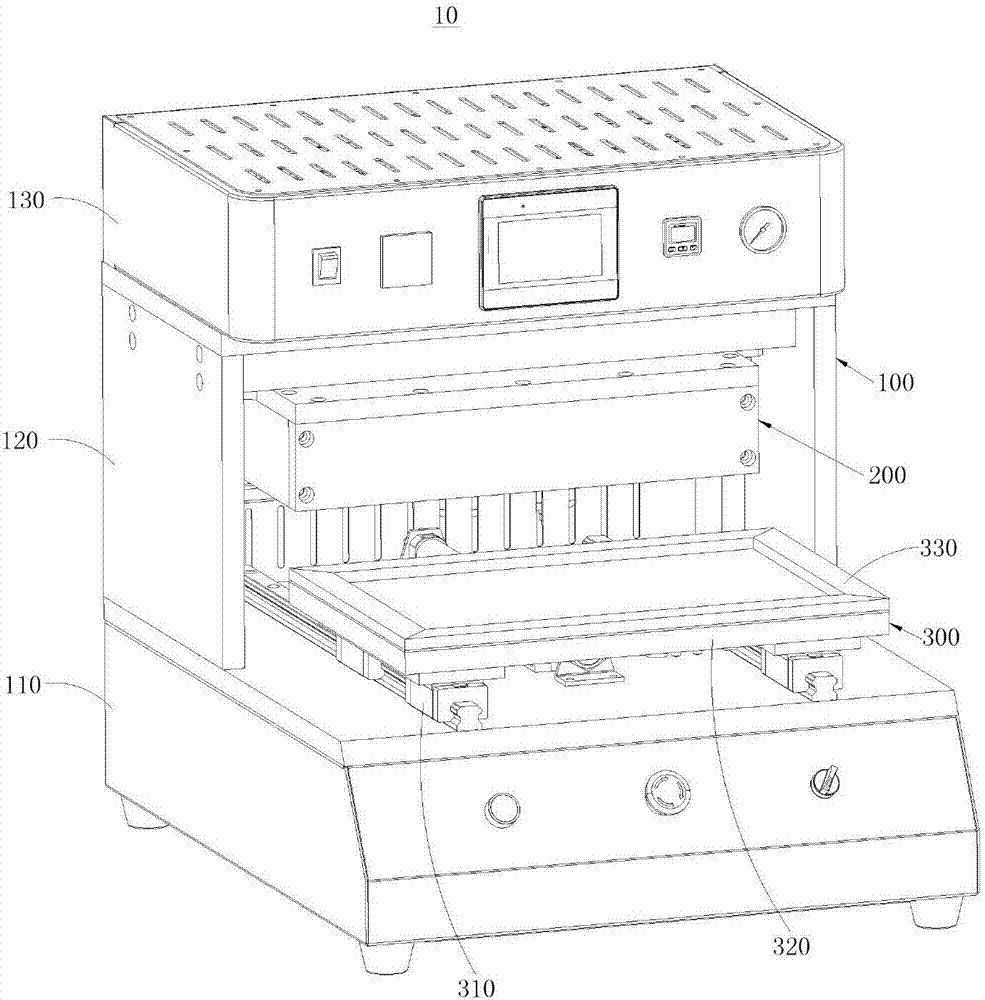
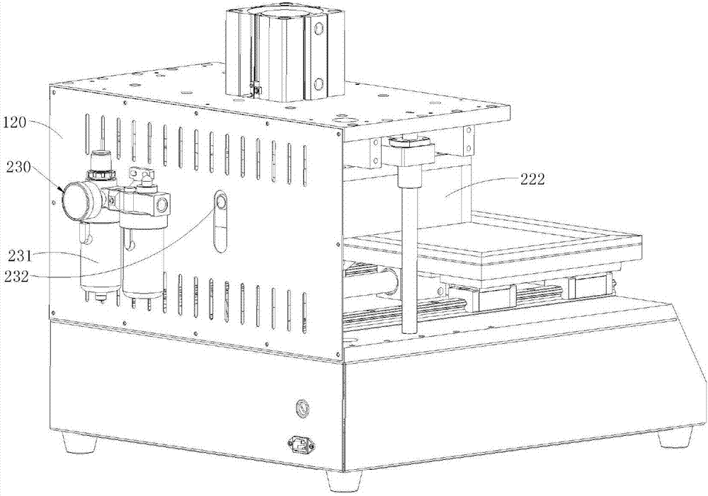
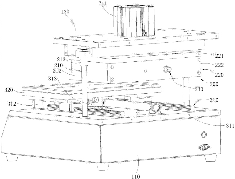
The invention relates to a laminating machine and a laminating method. The laminating machine comprises a mounting and supporting mechanism, a vacuum heating mechanism and a sliding sealing mechanism,wherein the mounting and supporting mechanism comprises a base, a support frame and a top box; the vacuum heating mechanism comprises a lifting device, a vacuum box, a vacuum device and a heating pressing assembly; the lifting device comprises a lifting cylinder, a guide rod and a sliding sleeve; the vacuum box comprises a mounting substrate and a mounting frame; the vacuum device comprises a mounting hose and a vacuum generation assembly; the heating pressing assembly comprises a mounting seat, a thermal baffle, a heating lower pressing plate and a heating pipe; the sliding sealing mechanismcomprises a sliding track device, a supporting device and a sealing device; the sliding track device is arranged on the base; the supporting device is arranged on the sliding track device; and the sealing device is arranged on the supporting device and is used for sealing a vacuum chamber together with the second end of the mounting frame. Therefore, bubbles in the product can be reduced in the product laminating process.

Description

technical field [0001] The invention relates to the technical field of bonding, in particular to a bonding machine and a bonding method. Background technique [0002] In some products, it is formed by laminating a multi-layer structure, for example, the first structural layer is bonded to the second structural layer through an adhesive layer, and the adhesive layer acts as a bond between the first structural layer and the second structural layer The attached middle adhesive layer, that is, the two sides of the adhesive layer are respectively attached to the first structural layer and the second structural layer. For example, in a liquid crystal module, its main functional structure is formed by bonding an adhesive layer to glass, wherein the adhesive layer serves as an intermediate adhesive layer for bonding the functional structure to the glass. [0003] At present, a laminating machine is usually used to realize the laminating operation of the product. First, the adhesive...

Claims


Application Information

Patent Timeline
IPC IPC(8): B32B37/06B32B37/12B32B37/10
CPCB32B37/06B32B37/10B32B37/12
Inventor 王俊黎成武
Owner 惠州保均新材科技有限公司
Why Eureka
Try Eureka