Electromagnetic valve combination-based cooling wind tunnel temperature control method

A temperature control method and solenoid valve technology, which is applied in the direction of temperature control using electric methods, auxiliary controllers with auxiliary heating devices, testing of machine/structural components, etc., can solve the problem of combining the number of solenoid valves in cooling wind tunnels Waiting for questions

Inactive Publication Date: 2018-04-06
NORTHWESTERN POLYTECHNICAL UNIV +1
View PDF6 Cites 6 Cited by
  • Summary
  • Abstract
  • Description
  • Claims
  • Application Information

AI Technical Summary

Problems solved by technology

[0003] There are many solenoid valves in the cooling wind tunnel, and there are many ways to combine them. There is no description of

Method used


Image

  • Electromagnetic valve combination-based cooling wind tunnel temperature control method
  • Electromagnetic valve combination-based cooling wind tunnel temperature control method
  • Electromagnetic valve combination-based cooling wind tunnel temperature control method

Examples


Embodiment Construction

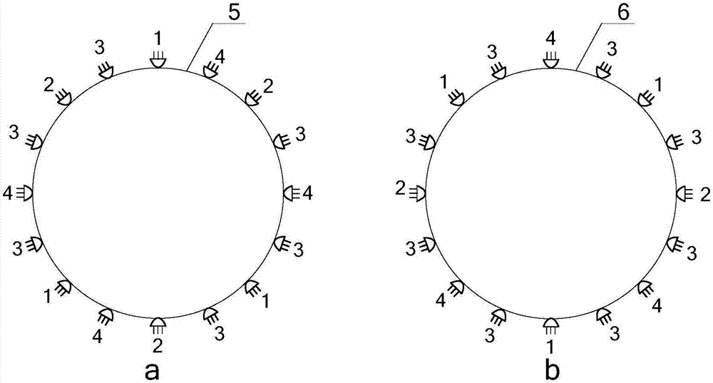
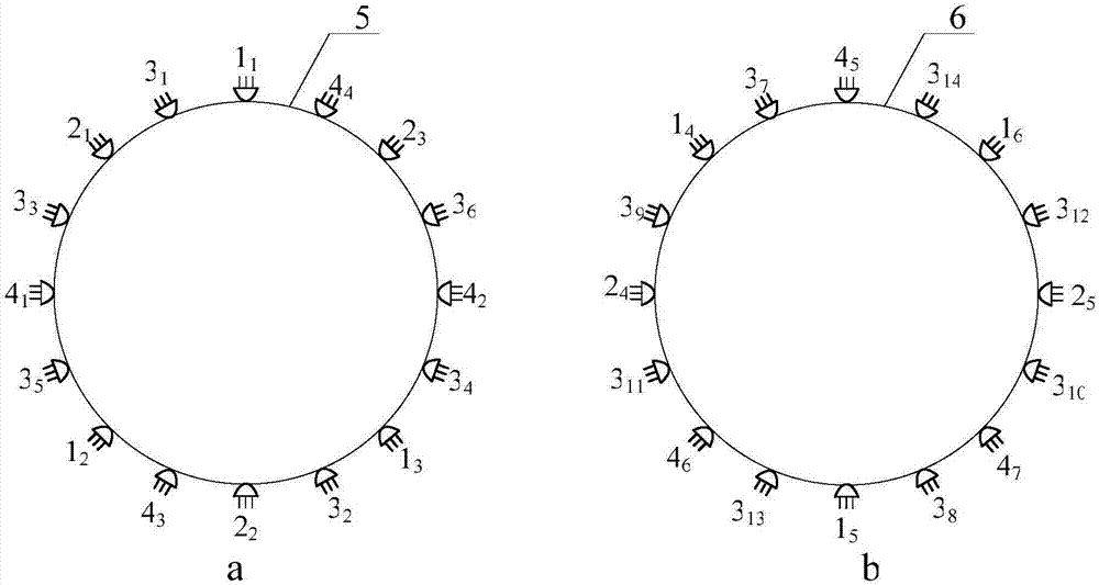
[0052] This embodiment is a cooling wind tunnel temperature control method based on a combination of solenoid valves. The cooling control system implements cooling by pushing and injecting liquid nitrogen, mainly based on control figure 1 The switch combination of the solenoid valve on the center liquid ring realizes the control of the injection flow, and then realizes the precise control of the temperature. figure 1 It is a side view of the wind tunnel along the air flow direction. The liquid nitrogen injection solenoid valve and nozzle are installed on the liquid collection ring, which is also used for liquid nitrogen filling. The solenoid valve group on the liquid collection ring includes two parts, which are divided into the upstream solenoid valve group and the downstream solenoid valve group. Solenoid valve group. figure 1 The upstream solenoid valve group in a is located between the compressor and the heat exchanger, and is specifically installed near the compressor sid...


PUM


Abstract

The invention relates to an electromagnetic valve combination-based cooling wind tunnel temperature control method. According to the method, firstly, a cooling control system is used for realizing thecooling function through extruding and pushing the liquid nitrogen. The control of the injection flow is realized through controlling a switch combination of an electromagnetic valve arranged on a liquid collecting ring, and then the accurate temperature control is realized. The liquid collecting ring is provided with a liquid nitrogen injection type electromagnetic valve and a nozzle used for filling the liquid nitrogen at the same time. An electromagnetic valve component on the liquid collecting ring is composed of an upstream electromagnetic valve set and a downstream electromagnetic valveset. The upstream electromagnetic valve set is located between a compressor and a heat exchanger. The distance between the upstream electromagnetic valve set and the tail end of the compressor is about 2 meters. The distance between the downstream electromagnetic valve set and the tail end of the compressor is about 4 meters. The nozzle is arranged at the tail end of the electromagnetic valve. The liquid nitrogen injection of the corresponding flow of the nozzle is realized by controlling an electromagnetic valve switch. According to the invention, through controlling the switch combination of the electromagnetic valve, the flow rate and the injection position of an injected refrigerant are controlled. Therefore, the cooling control of the wind tunnel is realized. The method has the advantages of high control precision, good temperature uniformity, simple control and good operability.

Description

technical field [0001] The invention relates to a temperature control method of a cooling wind tunnel based on a combination of electromagnetic valves, and belongs to the technical field of wind tunnel temperature control. Background technique [0002] The continuous wind tunnel uses a compressor to provide the power source to establish the required Mach number. The continuous wind tunnel can be divided into conventional wind tunnels, low temperature wind tunnels and cooling wind tunnels according to the operating temperature range. Conventional continuous wind tunnels are equipped with heat exchanger systems, through which the temperature of the airflow in the wind tunnel can be kept stable; cooling wind tunnels and low-temperature wind tunnels are equipped with liquid nitrogen / liquid ammonia injection systems, which can expand the test of wind tunnels by reducing the airflow temperature Reynolds number range. Taking liquid nitrogen injection as an example, the operating t...

Claims


Application Information

Patent Timeline
IPC IPC(8): G05D23/32G01M9/04
CPCG01M9/04G05D23/32
Inventor 陈旦张永双周廷波张国彪高超郗忠祥沈牟张正科胡旭
Owner NORTHWESTERN POLYTECHNICAL UNIV
Why Eureka
Try Eureka