Rapid brake device for three-phase asynchronous motor

A three-phase asynchronous and braking device technology, applied in the direction of motor generator control, motor/generator/inverter limiter, electrical components, etc., can solve the problem of untimely brake braking, troublesome use, troublesome users, etc. problems, achieve the effect of easy replacement and installation, and reduce the cost of use

Pending Publication Date: 2018-04-06
TAIZHOU ZHOUYI MECHANICAL&ELECTRICAL
View PDF0 Cites 2 Cited by
  • Summary
  • Abstract
  • Description
  • Claims
  • Application Information

AI Technical Summary

Problems solved by technology

from figure 1 It can be seen from the circuit that when SQ1 is disconnected, the motor M stops, the rectifier is powered off, and the power-off braking type electromagnetic brake is closed to brake. However, since the winding in the motor forms an inductance potential, after SQ1 is disconnected, the motor M There is also a potential for the rectifier. The rectifier is formed by diode half-wave rectification. As long as the voltage is greater than 0.7V, it will be turned on, so the inductance potential of the motor will be input from the AC side, and the voltage will be output from the DC side, resulting in output from the rectifier. power supply, resulting in the brakes not braking in time, causing a lot of trouble to the user
[0003] In view of this situation, the user has to make an external control circuit to control the rectifier and the brake, which increases the cost and troubles for the customer, so it is necessary to improve this

Method used


Image

  • Rapid brake device for three-phase asynchronous motor
  • Rapid brake device for three-phase asynchronous motor
  • Rapid brake device for three-phase asynchronous motor

Examples


Embodiment Construction

[0017] The following specific descriptions of the present invention are given by the examples, which are only used to further illustrate the present invention, and should not be construed as limiting the protection scope of the present invention.

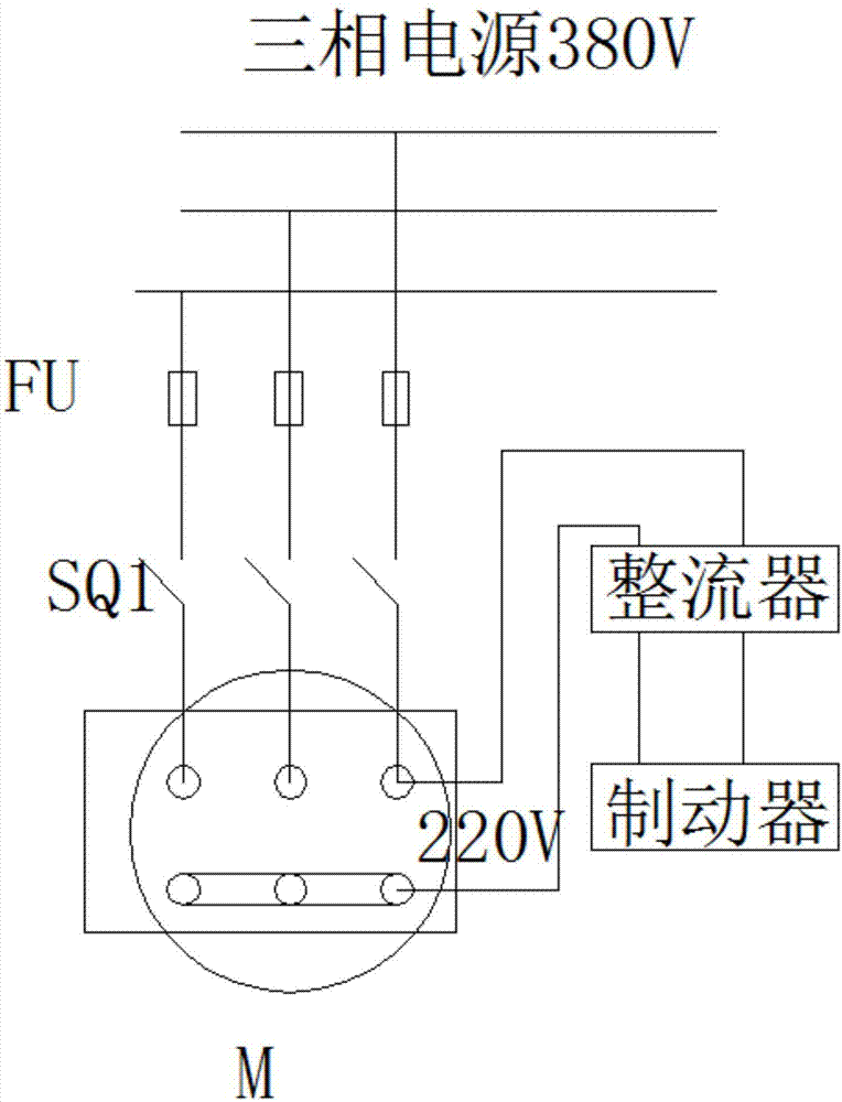
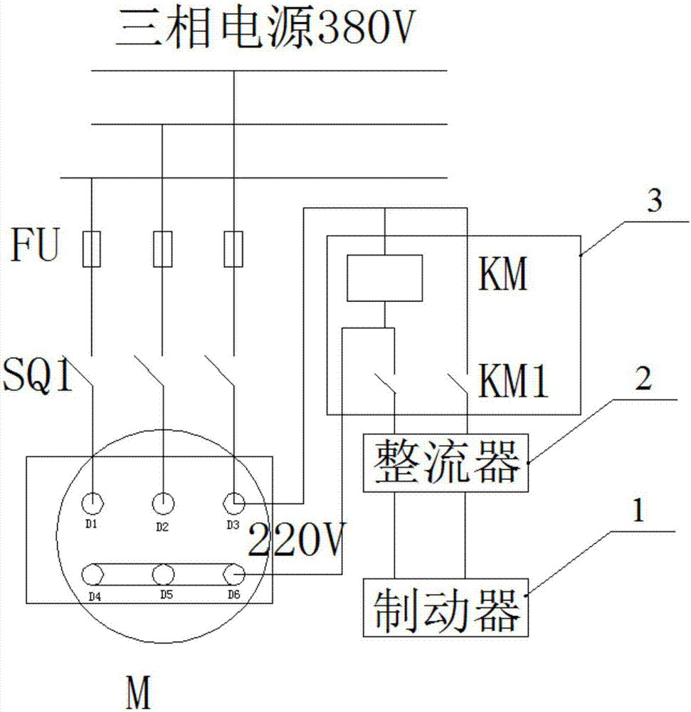
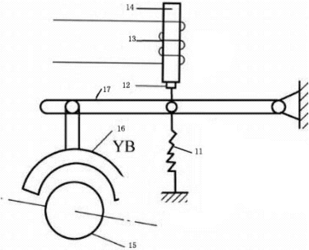
[0018] like Figure 2-3 The specific embodiment of the present invention shown includes a power-off braking type electromagnetic brake brake 1, and a rectifier 2 for converting alternating current into direct current, and the output end of the rectifier 2 is connected to a power-off braking type electromagnetic holding brake The brake 1 is provided with a DC working voltage, and also includes an AC electromagnetic contactor 3 . The three-phase stator windings of the three-phase asynchronous motor have two lead wire ends for each phase winding. One end is called the head end and the other end is called the end end. It is stipulated that the head end of the first phase winding is represented by D1, and the end is represented by D4; ...


PUM


Abstract

The present invention discloses a rapid brake device for a three-phase asynchronous motor. The brake device comprises a power-off brake electromagnetic band-type brake and a rectifier configured to convert an alternating current to a direct current, an output end of the rectifier is connected with the power-off brake electromagnetic band-type brake, and the rectifier supplies a direct current working voltage to the power-off brake electromagnetic band-type brake; and the brake device also comprises an alternating current electromagnetic contactor, two input ends of the alternating current electromagnetic contactor are respectively connected with a wiring front end and a wiring tail end of any one winding in a three-phase asynchronous motor, an output end of the alternating current electromagnetic contactor is connected with an input end of the rectifier, and the lowest closing voltage of an electromagnetic coil in the alternating current electromagnetic contactor is larger than an inductance potential of the winding when the three-phase asynchronous motor is powered off. The rapid brake device for the three-phase asynchronous motor is reasonable in structure design and low in cost,and can achieve rapid power-off brake.

Description

technical field [0001] The invention belongs to the technical field of motor control, and specifically refers to a fast braking device for a three-phase braking motor. Background technique [0002] After the power is cut off, the three-phase asynchronous motor needs to rotate for a period of time (or distance) to stop by inertia. However, in production, the motor is often required to stop quickly after the power is cut off. In the prior art, an electromagnetic brake is usually used to brake a three-phase asynchronous motor. The working principle of the brake is as follows: figure 1 said, figure 1 Among them, FU is a circuit three-phase circuit breaker, SQ1 is a motor switch, M is a three-phase asynchronous motor, and the input terminals of the rectifier are respectively connected to the wiring head and wiring end of any winding in the three-phase asynchronous motor. from figure 1 It can be seen from the circuit that when SQ1 is disconnected, the motor M stops, the rectif...

Claims


Application Information

Patent Timeline
IPC IPC(8): H02P3/18
CPCH02P3/18
Inventor 周华林海云
Owner TAIZHOU ZHOUYI MECHANICAL&ELECTRICAL
Why Eureka
Try Eureka