Device for reverse beating of screw and process

A technology for screwing and screwing, which is applied in metal processing, manufacturing tools, metal processing equipment, etc., can solve the problems of reducing the installation efficiency of fans, misalignment of two parts, and low efficiency, so as to avoid unstable screw installation, Avoid uneven force and improve work efficiency

Active Publication Date: 2018-04-10
南京力旷机电科技有限公司
View PDF6 Cites 1 Cited by
  • Summary
  • Abstract
  • Description
  • Claims
  • Application Information

AI Technical Summary

Problems solved by technology

[0002] At present, when assembling two components, it is often necessary to fix them by screwing. In the process of automatic screwing on the automation line, the phenomenon of screw deviation often occurs. The existing method often results in inaccurate alignment and takes a long time. ,low efficiency
[0003] During the assembly process of the fan, the upper and lower ends of the fan need to be fixed by screwing. The existing screwing device is carried out from top to bottom. If this kind of screwing device is used, the fan needs to be turned over and then fixed The screwing operation at the bottom is cumbersome, and it is prone to misalignment of the two parts when they are turned over. Manual adjustment is required, which greatly reduces the efficiency of fan installation.

Method used


Image

  • Device for reverse beating of screw and process
  • Device for reverse beating of screw and process
  • Device for reverse beating of screw and process

Examples


Embodiment Construction

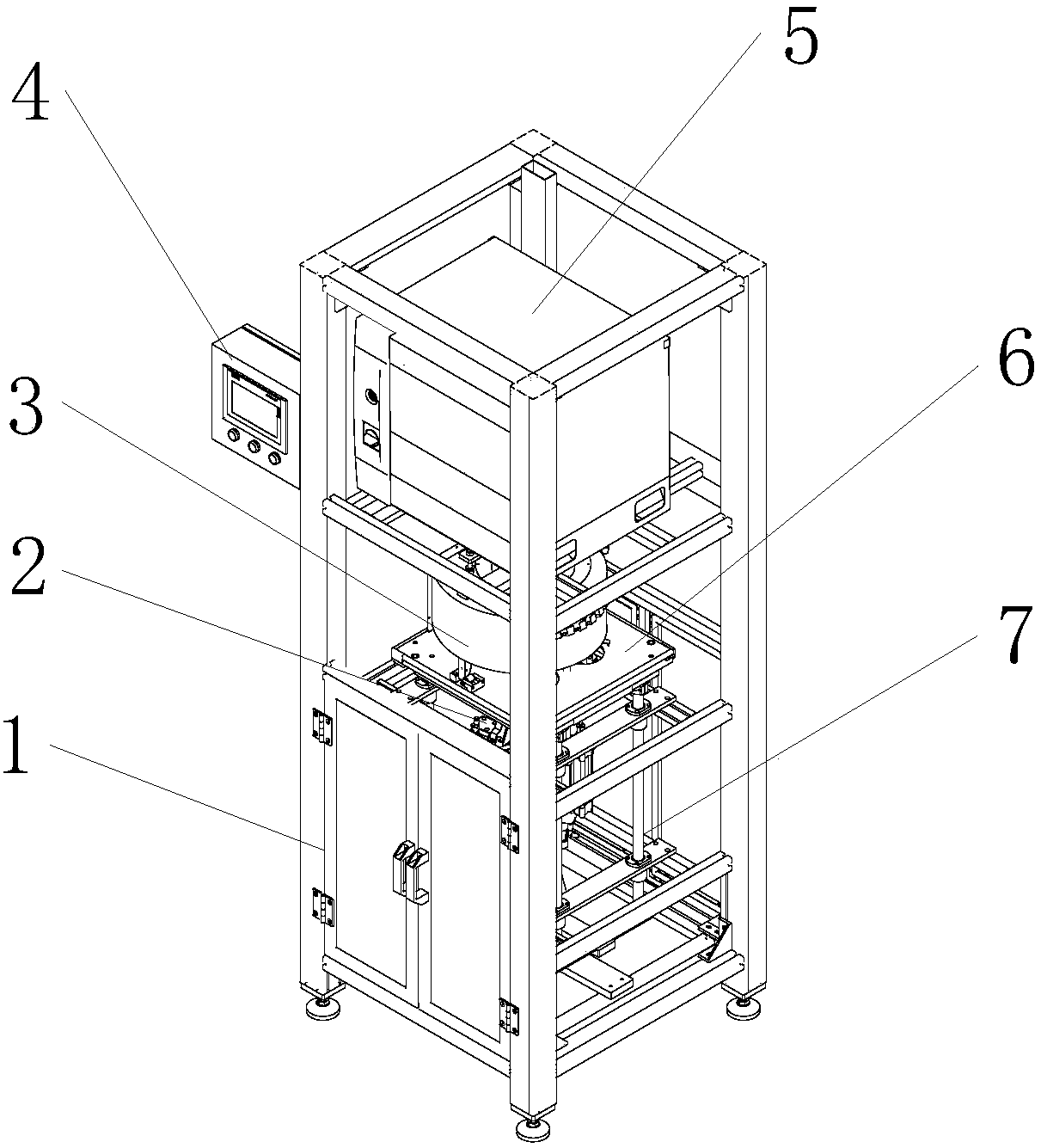
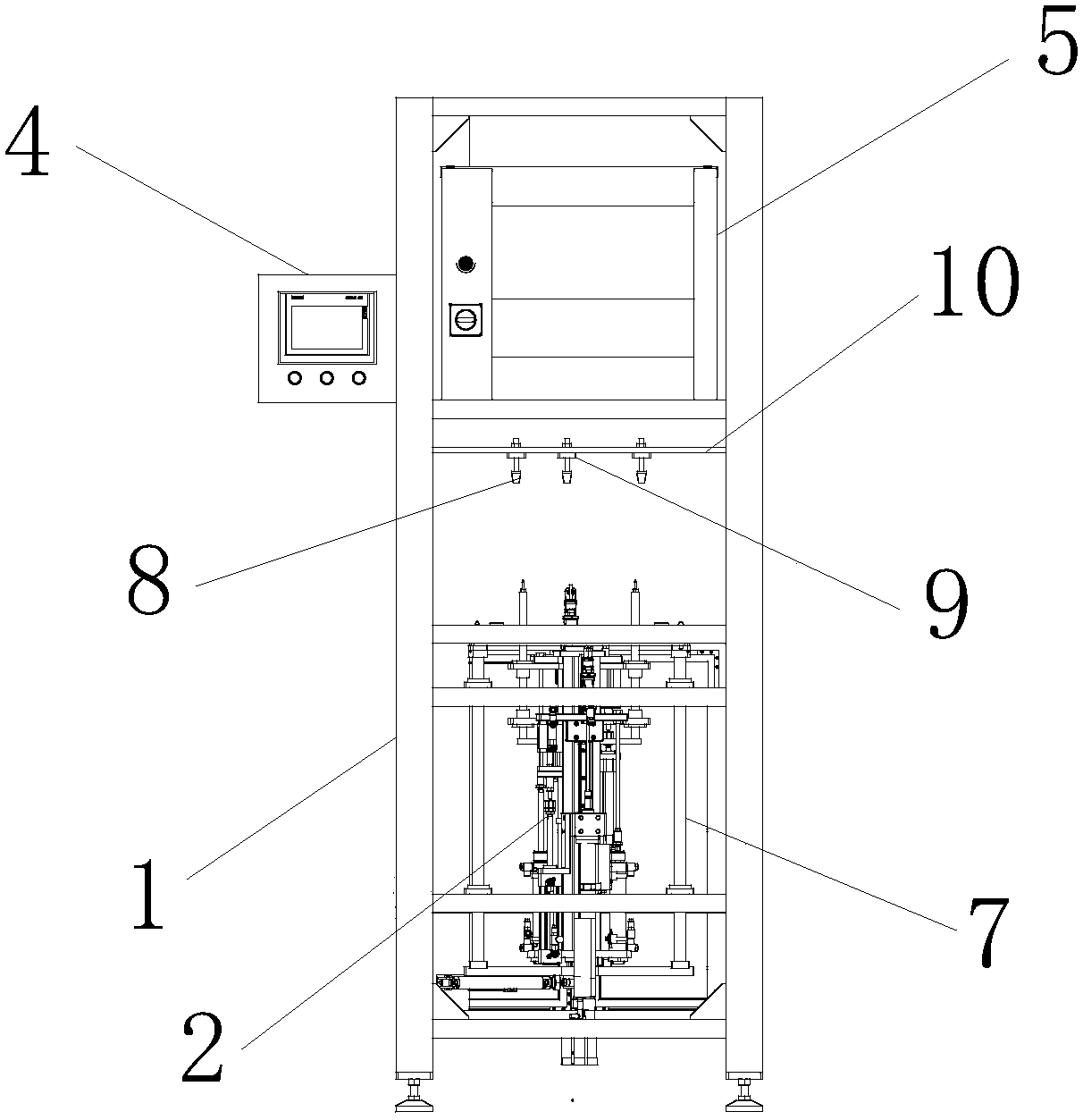
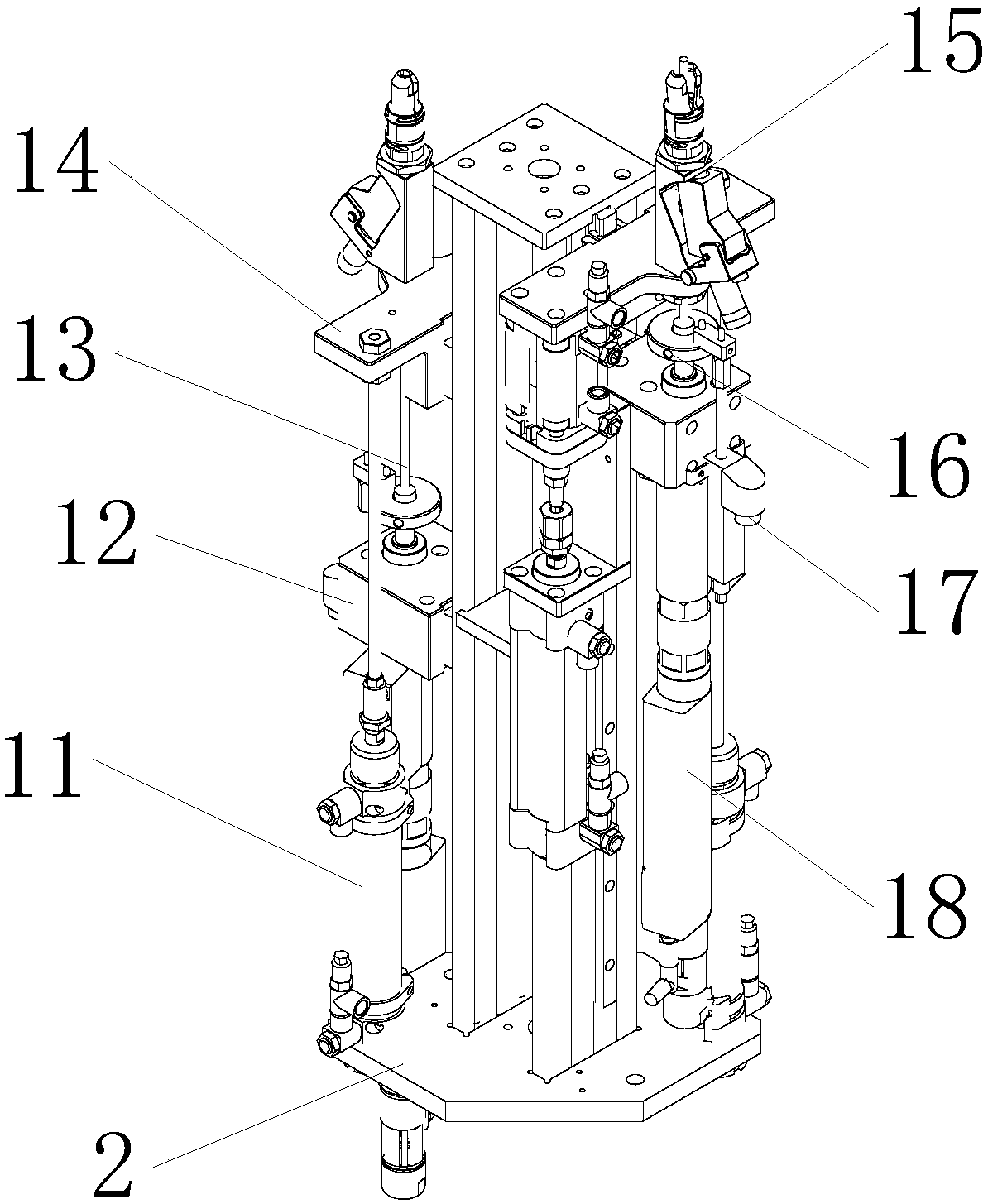
[0027] The following will clearly and completely describe the technical solutions in the embodiments of the present invention with reference to the accompanying drawings in the embodiments of the present invention. Obviously, the described embodiments are only some, not all, embodiments of the present invention.

[0028] Examples of the described embodiments are shown in the drawings, wherein like or similar reference numerals designate like or similar elements or elements having the same or similar functions throughout. The embodiments described below by referring to the figures are exemplary and are intended to explain the present invention and should not be construed as limiting the present invention.

[0029] In describing the present invention, it should be understood that the terms "center", "longitudinal", "transverse", "length", "width", "thickness", "upper", "lower", "front", " Back", "Left", "Right", "Vertical", "Horizontal", "Top", "Bottom", "Inner", "Outer", "Clock...


PUM


Abstract

The invention discloses a device for reverse beating of a screw and a process. The device comprises a frame body; a screw beating assembling body is arranged in an inner cavity of the frame body; thetwo sides of the screw beating assembling body are each provided with a jacking mechanism which is used for jacking up a sliding plate; the two sides of the sliding plate are in sliding connection with the frame body; a draught fan is fixed to the sliding plate; a fixed rod is arranged above the screw beating assembling body, and is provided with screw rod pressing feet which are fixed to the fixed rod through a pressing foot fixing plate; a control cabinet is arranged at the upper end of the frame body; a touch screen is arranged on one side of the frame body; the screw beating assembling body comprises a first telescopic rod, a second telescopic rod and a rotating shaft; a first connection block is arranged at one end of the first telescopic rod; a screw gun body is fixed to the first connection block; a second connection block is arranged at one end of the rotating shaft; a pushing rod is arranged at the upper end of the second connection block; and a second telescopic rod is arranged on one side of the second connection block. The device for reverse beating of the screw has the beneficial effects of being high in installing precision, automation degree and the like.

Description

technical field [0001] The invention relates to the technical field of blower fan processing, in particular to a screw driving device and process. Background technique [0002] At present, when assembling two components, it is often necessary to fix them by screwing. In the process of automatic screwing on the automation line, the phenomenon of screw deviation often occurs. The existing method often results in inaccurate alignment and takes a long time. ,low efficiency. [0003] During the assembly process of the fan, the upper and lower ends of the fan need to be fixed by screwing. The existing screwing device is carried out from top to bottom. If this kind of screwing device is used, the fan needs to be turned over and then fixed The screwing operation at the bottom is cumbersome and prone to misalignment of the two parts when turned over, requiring manual adjustment, which greatly reduces the efficiency of fan installation. Therefore, it is necessary to develop a bottom...

Claims


Application Information

Patent Timeline
Patent Type & Authority Applications(China)
IPC IPC(8): B23P19/06
CPCB23P19/001B23P19/069
Inventor 江慧李永兵
Owner 南京力旷机电科技有限公司
Why Eureka
Try Eureka