
Winch emergency release device and control method thereof

An emergency release and winch technology, which is applied in hoisting devices, clutches, mechanical equipment, etc., can solve the problems that the emergency release function cannot be realized, and achieve the effect of avoiding automatic brakes

Active Publication Date: 2018-04-10
WUHAN MARINE MACHINERY PLANT
View PDF8 Cites 7 Cited by
  • Summary
  • Abstract
  • Description
  • Claims
  • Application Information

AI Technical Summary

Problems solved by technology

[0006] In order to solve the problem that the emergency release function cannot be realized in the prior art, the embodiment of the present invention provides a winch emergency release device and its control method

Method used


Image

  • Winch emergency release device and control method thereof
  • Winch emergency release device and control method thereof
  • Winch emergency release device and control method thereof

Examples


Embodiment 1

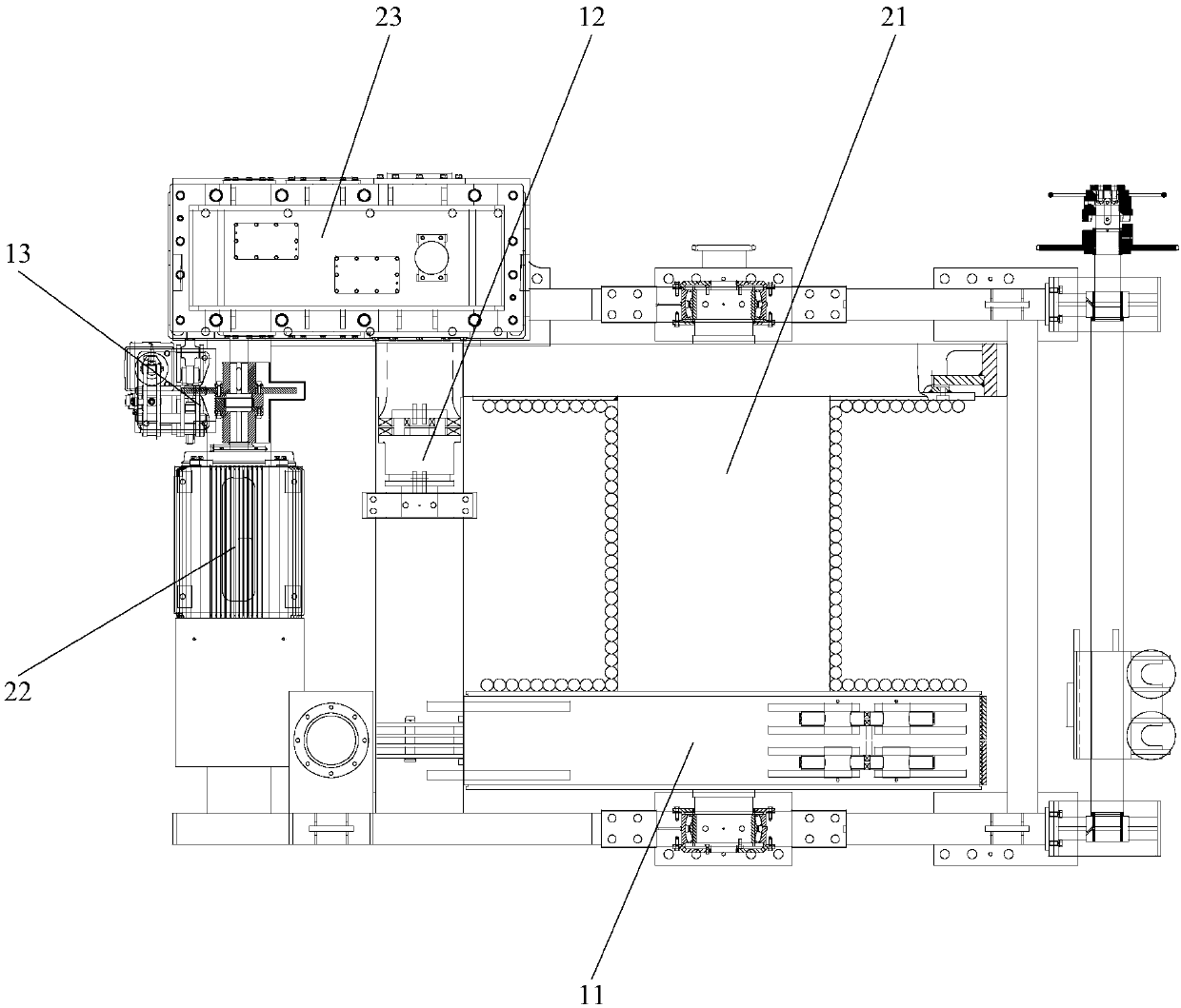
[0031] An embodiment of the present invention provides a winch emergency release device, see figure 1 The winch emergency release device includes a band brake 11, a clutch 12, an electromagnetic brake 13 and a control system. The band brake 11 is arranged on the drum 21 of the winch, and the clutch 12 drives the first motor 22 connecting the drum 21 and driving the drum to rotate. The brake 13 is provided on the output shaft of the first motor 22 .

[0032] In practical application, the drum 21 and the first motor 22 are respectively connected with the reducer 23 .

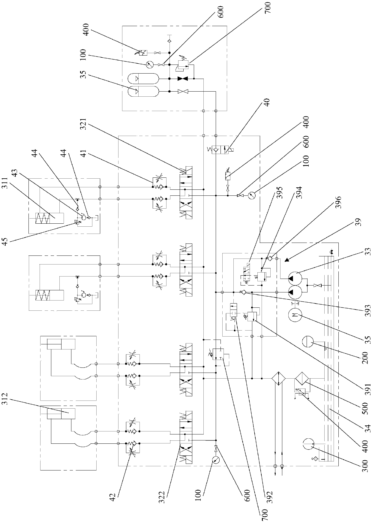
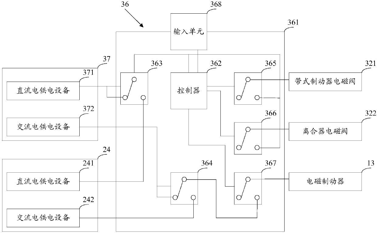
[0033] In this example, see figure 2 , Figure 3a and Figure 3b , the control system includes a band brake cylinder 311 for controlling the band brake 11, a clutch cylinder 312 for controlling the clutch 12, a band brake solenoid valve 321, a clutch solenoid valve 322, a hydraulic pump 33, an oil tank 34, an accumulator 35, control box 36 and emergency power supply 37.

[0034] Such as figure 2 As shown, th...

Embodiment 2

[0063] An embodiment of the present invention provides a control method for a winch emergency release device. The winch emergency release device adopts the winch emergency release device provided in Embodiment 1, see Figure 4 , the control methods include:

[0064] Step 501: Receive an emergency release command.

[0065] Step 502: When the winch is in a stopped state, the power supply system of the ship is used to drive the band brake to release and the clutch is disengaged.

[0066] Step 503: When the winch is in working state, if the ship is powered on, the power supply system of the ship is used to drive the band brake to release the brake, the clutch is separated, and the electromagnetic brake is released.

[0067] Step 504: When the winch is in working state, if the ship is in a power-off state, the accumulator is used to drive the band brake to release the brake, the clutch is separated, and the emergency power supply is used to drive the electromagnetic brake to relea...


PUM


Abstract

The invention discloses a winch emergency release device and a control method thereof, and belongs to the technical field of winch safety. The winch emergency release device comprises a belt brake, aclutch, an electromagnetic brake and a control system; the control system comprises a belt brake oil cylinder for controlling the belt brake, a clutch oil cylinder for controlling the clutch, a belt brake electromagnetic valve, a clutch electromagnetic valve, a hydraulic pump, an oil tank, an energy accumulator, a control box and an emergency power supply; the hydraulic pump respectively communicates with the oil tank, the energy accumulator, an oil inlet of the belt brake electromagnetic valve and an oil inlet of the clutch electromagnetic valve; an oil outlet of the belt brake electromagnetic valve communicates with a cylinder block of the belt brake oil cylinder; an oil outlet of the clutch electromagnetic valve communicates with a cylinder block of the clutch oil cylinder; and the emergency power supply and a ship power supply system supply electricity to the electromagnetic brake, the belt brake electromagnetic valve and the clutch electromagnetic valve through the control box. The winch emergency release device can realize the emergency release function.

Description

technical field [0001] The invention relates to the technical field of winch safety, in particular to a winch emergency release device and a control method thereof. Background technique [0002] A winch is a light and small lifting device that uses a drum to wind a wire rope or chain to lift or pull heavy objects, including electric winches and hydraulic winches. The emergency release device is a very important safety protection device on the ship, which is used to protect the safety of the winch and the hull in an emergency. [0003] The emergency release device of the electric winch includes a band brake set on the drum, a clutch set between the drum and the motor that drives the drum to rotate, an electromagnetic brake set on the output shaft of the motor, and a band brake for controlling, clutch And the control system of the electromagnetic brake. When performing emergency release, the control system drives the band brake to release the brake, and the clutch is disenga...

Claims


Application Information

Patent Timeline
IPC IPC(8): B66D1/54B66D5/10B66D5/30B66D5/26F16D48/06F16D48/10
CPCB66D1/54B66D5/10B66D5/26B66D5/30F16D48/064F16D48/10
Inventor 陶诗飞高卓周玉哲向鹏洋叶建高怡陈利鹏汪康平叶志坚
Owner WUHAN MARINE MACHINERY PLANT
Learn More