Continuous vapor deposition equipment

A technology of equipment and linear evaporation source, which is applied in vacuum evaporation plating, sputtering plating, ion implantation plating, etc., can solve the pollution of evaporation environment, affect the running time and output of evaporation equipment, and effectively evaporate the interference point source scope and other issues to achieve the effect of solving pollution

Active Publication Date: 2018-04-10
TRULY HUIZHOU SMART DISPLAY
View PDF8 Cites 1 Cited by
  • Summary
  • Abstract
  • Description
  • Claims
  • Application Information

AI Technical Summary

Problems solved by technology

Although the principles of the two films are basically the same, there are differences in the way of film preparation: point source evaporation equipment, the position of the effective evaporation source is relatively fixed, and the glass is rotated to ensure the uniformity of the prepared film; while the linear evaporation source, the glass is fixed, The uniformity of the thin film is ensured by moving the linear evaporation source at a constant speed. Relatively speaking, the uniformity of the thin film prepared by the linear evaporation source is more advantageous than that of the point source; since the material added to the crucible is limited at one time, it is necessary to periodically open the cavity and refill the material , this method pollutes the evaporation environment inside the cavity and affects the running time and output of the evaporation equipment
[0003] Patent No. CN 107267920B "Evaporation Equipment, Crucible and Evaporation Method" patent discloses a continuous evaporation equipment and operation method. It can be seen from the circular distribution of the evaporation source crucible of the evaporation equipment that it is mainly aimed at point source evaporation equipment. The effective evaporation crucible in the point source and the crucible in the storage chamber are replaced by a telescopic lifting and rotating lifting mechanism. This design has limitations, because the linear crucible is large in size and heavy in weight, and the linear crucibles are arranged linearly. , there is also a heat shield on the upper part of the nozzle. Using the method described in this patent is not suitable for linear evaporation source evaporation equipment, and it is impossible to replace the linear source crucible inside the evaporation source without opening the cavity to achieve continuous evaporation. The purpose of plating; and the retractable lifting rotary lifting mechanism is located in the center of the point source, which will interfere with the effective evaporation range of the point source and affect the uniformity of film thickness. At the same time, organic materials will be deposited on the retractable lifting rotary lifting mechanism during evaporation. When the mechanism moves, it will cause the material to drop, and even cause the deposited material to fall to the position of the point source nozzle, resulting in hole plugging

Method used


Image

  • Continuous vapor deposition equipment
  • Continuous vapor deposition equipment
  • Continuous vapor deposition equipment

Examples


Embodiment

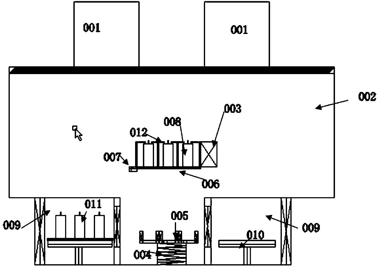
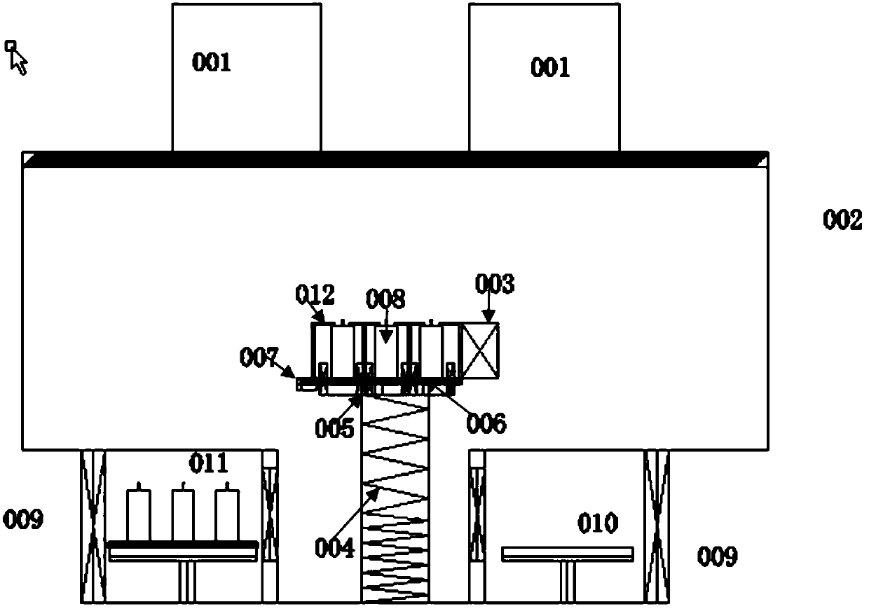
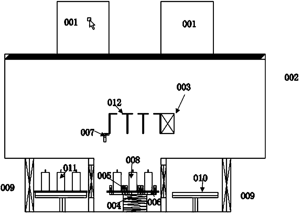
[0027] This embodiment provides a continuous evaporation equipment, such as Figures 1 to 4 As shown, it includes a main cavity 002 and a linear evaporation source located in the main cavity 002, a linear crucible carrying platform 006 carrying a linear crucible, a lifting unit 004, a clamp unit 007, and two linear crucible vacuum conversion The cavity 009 and the handling unit 010 respectively located in the linear crucible vacuum conversion cavity 009, wherein the linear crucible vacuum conversion cavity 009 is used to place the linear crucible carrying platform 006, and the handling unit 010 is used for The linear crucible carrying platform 006 is transferred between the linear crucible vacuum conversion cavity 009 and the lifting unit 004, and the lifting unit 004 is used to disengage the linear crucible carrying platform 006 or put it into the linear crucible carrying platform 006. An evaporation source, the clamp unit 007 is used to fix the linear crucible carrying platf...


PUM


Abstract

The invention relates to the field of vapor deposition and discloses continuous vapor deposition equipment. The equipment comprises a main cavity, a linear evaporation source located in the main cavity, a linear crucible bearing platform for bearing a linear crucible and a lifting unit and further comprises two linear crucible vacuum transfer cavities and carrying units located in the linear crucible vacuum transfer cavities correspondingly. The linear crucible vacuum transfer cavities are used for storing the linear crucible bearing platform. The carrying units are used for transferring the linear crucible bearing platform between the linear crucible vacuum transfer cavities and the lifting unit. The lifting unit is used for enabling the linear crucible platform to be separated from or beplaced into the linear evaporation source. The linear crucible vacuum transfer cavities and the main cavity are provided with independent vaccumizing devices correspondingly. By the adoption of the technical scheme, product performance is improved, effective production time of the equipment is prolonged, and the purpose of long-time continuous production is achieved.

Description

technical field [0001] The invention relates to the field of evaporation, in particular to a continuous evaporation equipment. Background technique [0002] In the production of OLED (Organic Light-Emitting Diode, Organic Light-Emitting Diode), the existing evaporation equipment is mainly divided into linear source evaporation equipment and point source evaporation equipment, both of which are based on the evaporation chamber in the atmospheric environment. Organic materials are added to the crucible in the body, and after being evacuated to a high vacuum environment, the crucible is heated to vaporize the organic materials, thereby preparing the organic thin film of the OLED device. Although the principles of the two films are basically the same, there are differences in the way of film preparation: point source evaporation equipment, the position of the effective evaporation source is relatively fixed, and the glass is rotated to ensure the uniformity of the prepared film;...

Claims


Application Information

Patent Timeline
Patent Type & Authority Applications(China)
IPC IPC(8): C23C14/24C23C14/56
CPCC23C14/243C23C14/56
Inventor 曾兴中蔡晓义柯贤军苏君海李建华
Owner TRULY HUIZHOU SMART DISPLAY
Why Eureka
Try Eureka