A fan air inlet device

An inlet and fan technology, applied in the field of fan inlet and inlet devices, can solve the problems of increasing engine noise, occupying hanging space, affecting aircraft comfort and safety, etc., and achieve the effect of reducing noise and solving pressure fluctuations

Active Publication Date: 2020-02-11
COMAC +1
View PDF5 Cites 0 Cited by
  • Summary
  • Abstract
  • Description
  • Claims
  • Application Information

AI Technical Summary

Problems solved by technology

This pressure fluctuation phenomenon will significantly increase the noise of the engine, and at the same time cause the vibration level of the structure or components to exceed the safe setting value, all of which will affect the comfort and safety of the aircraft
[0004] In order to avoid the problem of pressure fluctuation, the existing civil aircraft system usually increases the length of the fan inlet, but this solution often causes the fan inlet device to be very large, taking up a lot of hanging space and other problems

Method used


Image

  • A fan air inlet device
  • A fan air inlet device
  • A fan air inlet device

Examples


Embodiment Construction

[0017] In the following detailed description of the preferred embodiment, reference is made to the accompanying drawings which form a part hereof. The accompanying drawings show, by way of example, specific embodiments in which the invention can be practiced. The illustrated embodiments are not intended to be exhaustive of all embodiments in accordance with the invention. It is to be understood that other embodiments may be utilized and structural or logical changes may be made without departing from the scope of the present invention.

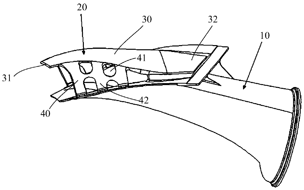
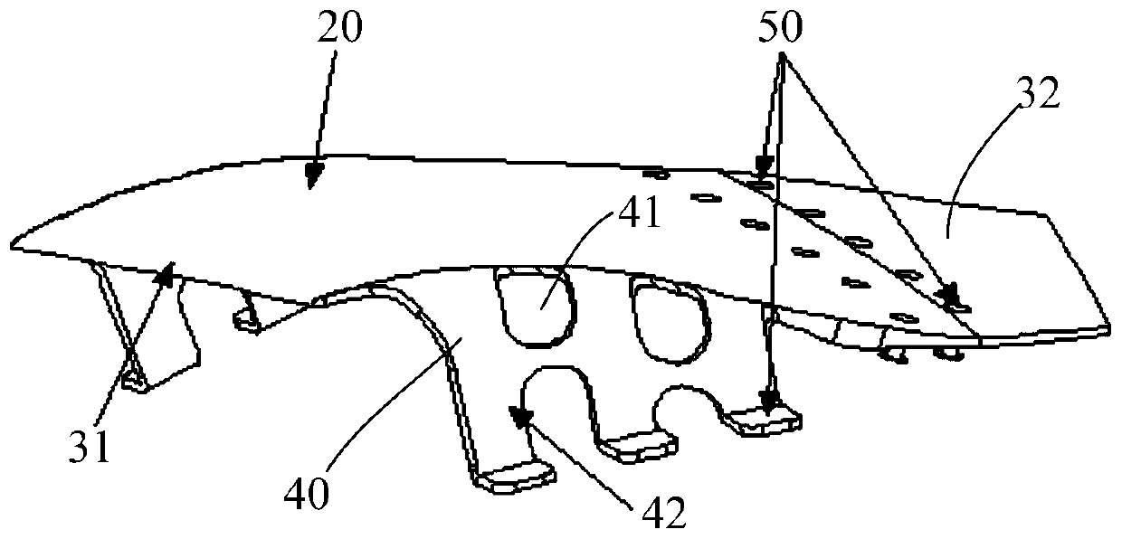
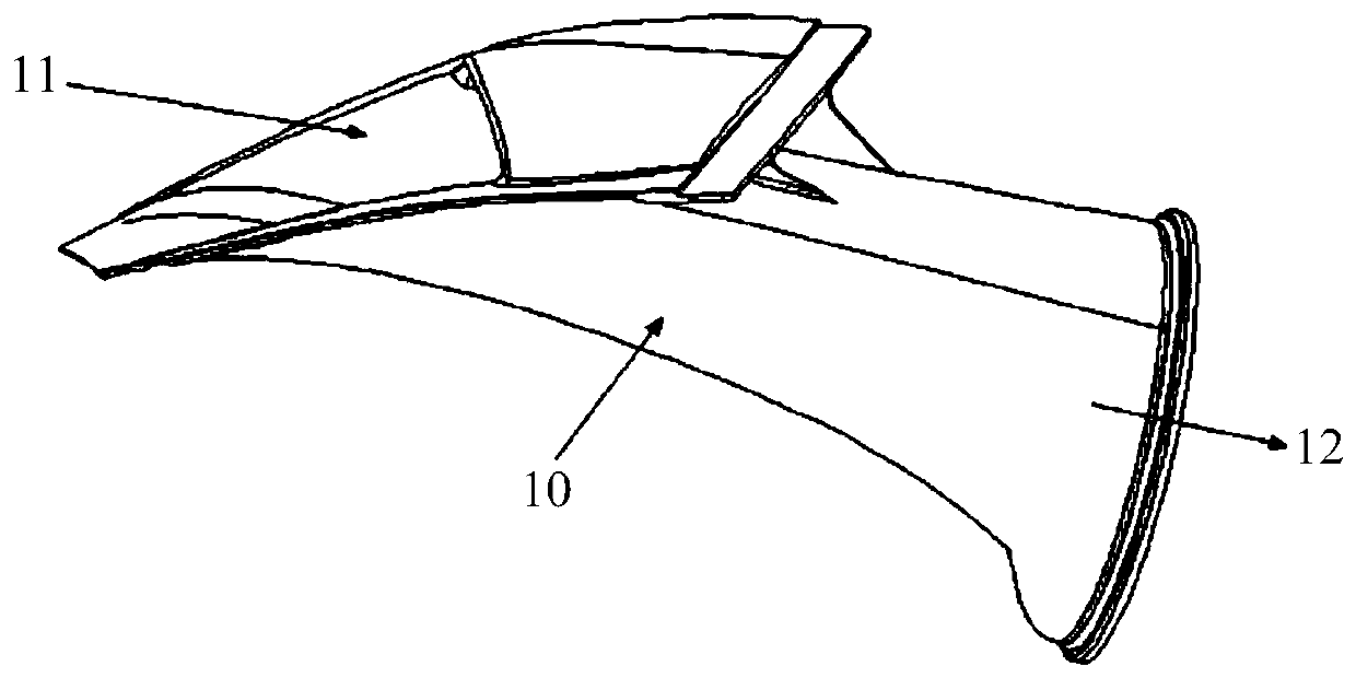
[0018] Such as Figure 1 to Figure 3 As shown in , the fan air intake device includes an air intake duct 10 and an air intake cap 20 . The air inlet duct 10 includes a square inlet 11 and a circular outlet 12. The airflow enters the air inlet duct 10 from the inlet 11, and the outlet 12 is connected with compensating devices, fan air valves and other devices. The intake cap 20 includes a cap body 30 and two cap side portions 40 extending fr...


PUM


Abstract

The invention provides a fan gas inlet device which comprises a gas inlet pipeline and a gas inlet cap. The gas inlet cap comprises a cap body and two cap side portions extending from the two sides ofthe cap body correspondingly. The cap body is provided with a front edge lip and a rear edge part. A gas inlet is formed between the front edge lip and the gas inlet pipeline. The rear edge part is connected to the gas inlet pipeline. The cap side portions are connected to the gas inlet pipeline and are provided with gas inlet holes. According to the fan gas inlet device, through the manner of changing the condition of a flow field in the fan gas inlet by arranging the gas inlet cap, the pressure fluctuation condition is pressed within an acceptable range, and therefore the problem of pressure fluctuation is solved.

Description

technical field [0001] The invention relates to a fan air inlet device, in particular to a fan air inlet device for eliminating pressure fluctuations in an aircraft fan bleed air system. Background technique [0002] In civil aircraft systems, engines are not only used to provide propulsion for the aircraft, but also to provide power and air sources. For example, the air source system of a civil aircraft usually draws high-temperature and high-pressure gas from the engine for use in downstream gas systems, such as air conditioning systems, anti-icing systems, etc. [0003] Since the high-temperature and high-pressure gas is drawn from the engine, the current design of the air source system requires cooling of the drawn gas. Generally, this cooling needs to be realized through a heat exchanger, and the cold side gas of the above-mentioned heat exchanger will be taken from the engine. The fan is led out from the external duct, and enters the cold side of the heat exchanger th...

Claims


Application Information

Patent Timeline
Patent Type & Authority Patents(China)
IPC IPC(8): F04D29/40F04D29/66
CPCF04D29/403F04D29/661F05D2250/51
Inventor 朱禹王磊杜楠楠刘超孙艳阳彭丹祺
Owner COMAC
Why Eureka
Try Eureka