
Power unit test system

A power unit and test system technology, which is applied in the direction of electric power measurement by using pulse modulation, can solve the problems of high test cost, troublesome, unusable frequency converter, etc., and achieve the effect of reducing test cost and simple test operation

Inactive Publication Date: 2018-04-10
BEIJING HELI ELECTRICAL TRANSMISSION CONTROL TECH
View PDF8 Cites 6 Cited by
  • Summary
  • Abstract
  • Description
  • Claims
  • Application Information

AI Technical Summary

Problems solved by technology

[0005] When testing the power unit, it is cumbersome to assemble the inverter; and once a power unit in the inverter fails the test, the entire inverter cannot be used, resulting in high testing costs

Method used


Image

  • Power unit test system
  • Power unit test system
  • Power unit test system

Examples


Embodiment

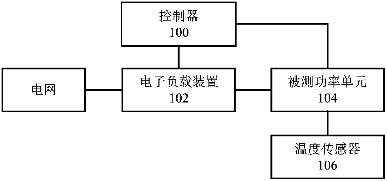
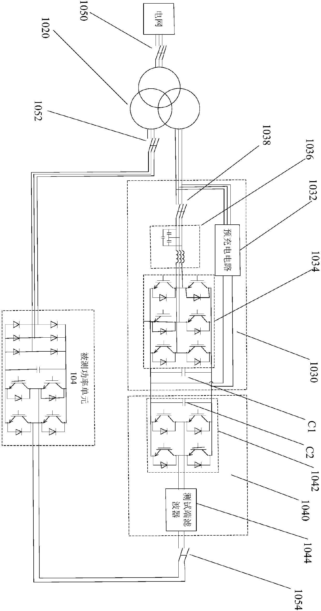
[0062] see Figure 1-2 As shown in the schematic structural diagram of the power unit test system, this embodiment proposes a power unit test system, including: a controller 100, an electronic load device 102, a power unit under test 104, and a temperature sensor 106;

[0063] The electronic load device 102 is connected to the controller 100 and the power unit under test 104 respectively; the power unit 104 under test is also connected to the controller 100 and the temperature sensor 106 respectively.

[0064] The controller 100 is configured to start the electronic load device 100 and the power unit under test 104 so that the electronic load device 102 and the power unit under test 104 respectively receive AC power from the power grid.

[0065] The power unit under test 104 is configured to work in a full-power working state driven by the AC power, and output a first AC voltage to the electronic load device 102 .

[0066] The first AC voltage is a sinusoidal PWM voltage.

...


PUM


Abstract

The invention provides a power unit test system, which tests a power unit under test by setting an electronic load device. Compared with the related art in which multiple power units need to be assembled into a frequency converter for testing, the power unit test system is simple in test operation and can test a single power unit by the electronic load device without assembling multiple power units into a frequency converter, even if the test result of the power unit is not qualified, the frequency converter can be simply assembled without using the power unit, the defect that the entire frequency converter cannot be used if one power unit fails the test is avoided, and the test cost is greatly reduced.

Description

technical field [0001] The present invention relates to the technical field of electronic circuits, in particular to a power unit testing system. Background technique [0002] At present, the frequency converter is a power control device that controls the AC motor by changing the frequency of the motor's operating power supply. Inverters can be divided into voltage source inverters and current source inverters. Among them, voltage source inverters are divided into two-level inverters, three-level inverters, and five-level inverters according to the number of levels that can be output by each phase. Flat inverters and more level inverters, etc. Among them, inverters with more than two levels are collectively referred to as multi-level inverters. Voltage source multilevel inverters are divided into two types: common DC bus structure and transformer isolation structure, and inverters with transformer isolation structure are also called unit series high-voltage inverters. In t...

Claims


Application Information

Patent Timeline
Patent Type & Authority Applications(China)
IPC IPC(8): G01R21/127
CPCG01R21/127
Inventor 马永健李凯
Owner BEIJING HELI ELECTRICAL TRANSMISSION CONTROL TECH
Learn More