A head-wearing multi-depth three-dimensional image display system and display method

A technology of stereoscopic image and display system, applied in optical components, optics, instruments, etc., can solve problems such as visual fatigue

Active Publication Date: 2018-04-10
LIGHTIN INC
View PDF28 Cites 25 Cited by
  • Summary
  • Abstract
  • Description
  • Claims
  • Application Information

AI Technical Summary

Problems solved by technology

With the development of VR and AR, many companies have developed various wearable stereoscopic display devices, but because most of the display solutions they adopt are single-depth image information, which rely on the principle of binocular parallax, when the display When the size of the front and back of the object, the size of the display screen, and the distance between the observer and the display screen are not large, the user will feel dizzy after long-term use, resulting in visual fatigue, and it is not suitable for children and special groups

Method used


Image

  • A head-wearing multi-depth three-dimensional image display system and display method
  • A head-wearing multi-depth three-dimensional image display system and display method
  • A head-wearing multi-depth three-dimensional image display system and display method

Examples


Embodiment 1

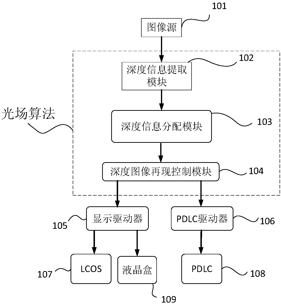
[0084] A head-mounted multi-depth stereoscopic display system, comprising:

[0085] The depth information extraction module extracts the color data and the three-dimensional coordinate data of the pixel points in the three-dimensional image, and transmits it to the depth information distribution module;

[0086] The depth information allocation module allocates all pixel points into several pixel point groups with different spatial depth ranges;

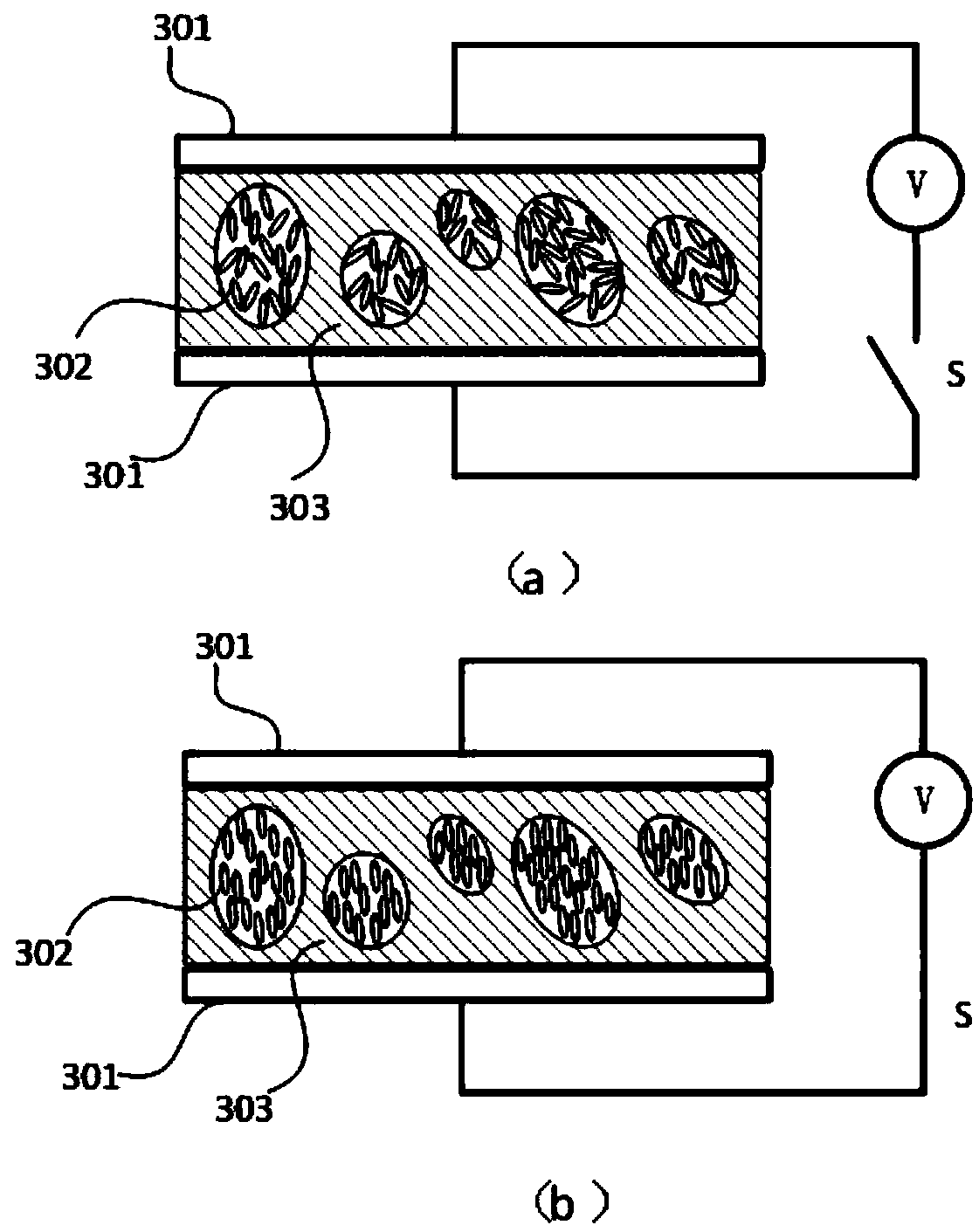
[0087] Several layers of PDLC with controllable transparent state / scattering state;

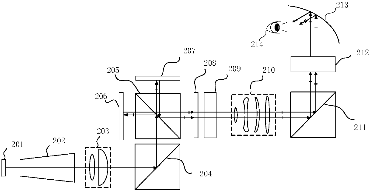
[0088] The projection unit, including a micro display chip and a projection lens, selectively projects each pixel point group on the PDLC of the corresponding depth at a certain frequency to generate a relay stereo image visible in the multi-plane optical unit;

[0089] The vision unit, including the eyepiece lens, projects the relayed stereoscopic image in the multi-plane optical unit to the human eye.

[0090] like figure 1 As shown, the contro...

Embodiment 2

[0138] Another embodiment of the head-mounted multi-depth stereoscopic display system is as follows: Figure 8 As shown, compared with Embodiment 1, a gaze tracking module 110 is added.

[0139] like Figure 8 , 9 As shown, it more clearly expresses the image processing process after matching with the gaze tracking module. After the image source is generated, the depth information extraction module obtains the RGB and three-dimensional coordinate data of each pixel of the image source, and at the same time, the gaze information obtained at this moment is packaged together and sent to the depth information distribution module.

[0140]The assigning module assigns the image source pixel and its surrounding pixels at the gaze depth to the PDLC layer corresponding to the depth for display. When the gaze depth is exactly the same as the depth set by the PDLC, the pixels are assigned to the PDLC layer for display; when the gaze depth is between the preset six depths, the pixels a...

Embodiment 3

[0146] The head-mounted multi-depth stereoscopic display system of another embodiment, as an extension of Embodiment 2, reduces the number of elements for selectively executing the transparent state / scattering state switching mode compared to Embodiment 2, Thereby, the restriction on the refresh rate of the projection unit is further reduced.

[0147] The control method of Embodiment 3 is basically the same as the control method of Embodiment 2, and the main difference lies in the image processing process after integrating the gaze tracking module. Therefore, the following focuses on describing the differences between Embodiment 3 and Embodiment 2 in the subsequent image processing process.

[0148] like Figure 9 , 11, in Example 2, we have described that the human eye can only see the image within the 5° field of view, and the image outside the 5° field of view is blurred by the human eye. , which exists as the background of the image within the 5° field of view that the h...


PUM


Abstract

The invention provides a head-wearing multi-depth three-dimensional image display system comprising a processing unit, a multi-plane optical unit, a projection unit, and a visual unit. The processingunit receives three-dimensional image information, extracting color data and three-dimensional coordinate data representing depth information of each pixel point in the three-dimensional image, and distributing all the pixel points into a plurality of pixel point groups corresponding to different space depths according to the three-dimensional coordinates of the pixel points. The multi-plane optical unit comprises a plurality of layers of transparent state / scattering state-controllable transparent scattering elements. The projection unit selectively projects each pixel point group to a transparent scattering element representing the corresponding depth with a certain frequency to generate a relay three-dimensional image which is visual in the multi-plane optical unit. The visual unit comprises an eyepiece lens which can project the relay three-dimensional images in the multi-plane optical unit to human eyes. The three-dimensional display effect of the display system is good; the display system can ease visual fatigue of users. The invention also provides a multi-depth three-dimensional image display method.

Description

technical field [0001] The invention relates to the field of display technology, in particular to a head-mounted multi-depth stereoscopic image display system and a display method. Background technique [0002] Objects in the real world are all three-dimensional, and the current mainstream display technology is still flat display technology, which gradually fails to meet people's visual needs, while stereoscopic display technology allows observers to see all aspects of objects. To a certain extent, the observer has an immersive feeling and a more realistic sense. Stereoscopic display technology is also considered to be the ultimate form of display technology. In recent years, many researchers have explored stereoscopic display technology and developed various stereoscopic display solutions. [0003] Stereoscopic display technology can be roughly divided into two categories: head-mounted and naked-eye. In the head-mounted stereoscopic display technology, observers need to ...

Claims


Application Information

Patent Timeline
Patent Type & Authority Applications(China)
IPC IPC(8): G02B27/22
CPCG02B30/34
Inventor 张卓鹏魏一振钱伟
Owner LIGHTIN INC
Why Eureka
Try Eureka