Fertilizer discharger for no-tillage seed drill and fertilizer discharging device using fertilizer discharger

The technology of a fertilizer discharging device and a seed drill is applied in the directions of fertilizer application device, fertilizer distributor, application, etc., which can solve the problems of low fertilizer discharging efficiency, uneven fertilizer discharging, and difficulty in adjusting the fertilizer discharging speed, and achieve the effect of uniform fertilizer discharging.

Pending Publication Date: 2018-04-13
襄阳市弘乾农业机械销售有限公司
View PDF1 Cites 2 Cited by
  • Summary
  • Abstract
  • Description
  • Claims
  • Application Information

AI Technical Summary

Problems solved by technology

[0004] In order to overcome the problems of uneven fertilizer discharge, difficult adjustment of fertilizer discharge speed and low fertilizer discharge efficiency in the fertilizer discharger in the prior art, the invention discloses a fertilizer discharger for a no-tillage seed drill, which includes a fertilizer discharge box, a fertilizer discharge grooved wheel, short fertilizer discharge pipe and fertilizer discharge chute, the fertilizer discharge grooved wheel is located inside the fertilizer discharge box; the short fertilizer discharge pipe is fixedly installed at the bottom outlet of the fertilizer discharge box and connected with the fertilizer discharge The inside of the box is connected, and the fertilizer discharge chute is composed of a chute bottom plate and chute side plates located on both sides of the chute bottom plate and having an angle of 90° with the chute bottom plate. on the surface of the bottom plate of the chute

Method used


Image

  • Fertilizer discharger for no-tillage seed drill and fertilizer discharging device using fertilizer discharger
  • Fertilizer discharger for no-tillage seed drill and fertilizer discharging device using fertilizer discharger
  • Fertilizer discharger for no-tillage seed drill and fertilizer discharging device using fertilizer discharger

Examples


Embodiment Construction

[0022] The present invention will be described in further detail below in conjunction with the embodiments and accompanying drawings. It should be understood that the specific embodiments described here are only used to explain the present invention, not to limit the present invention.

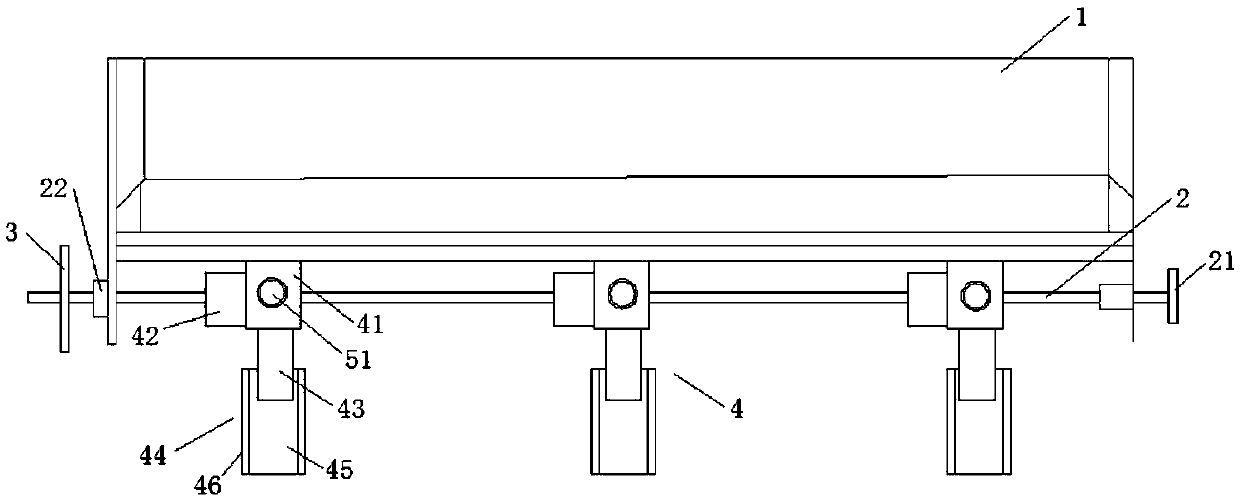
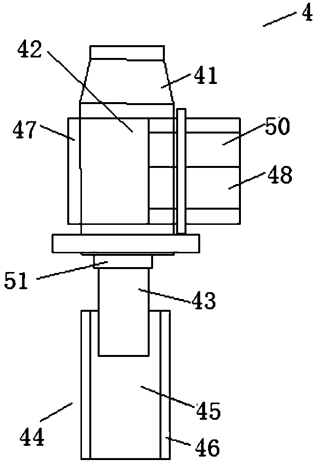
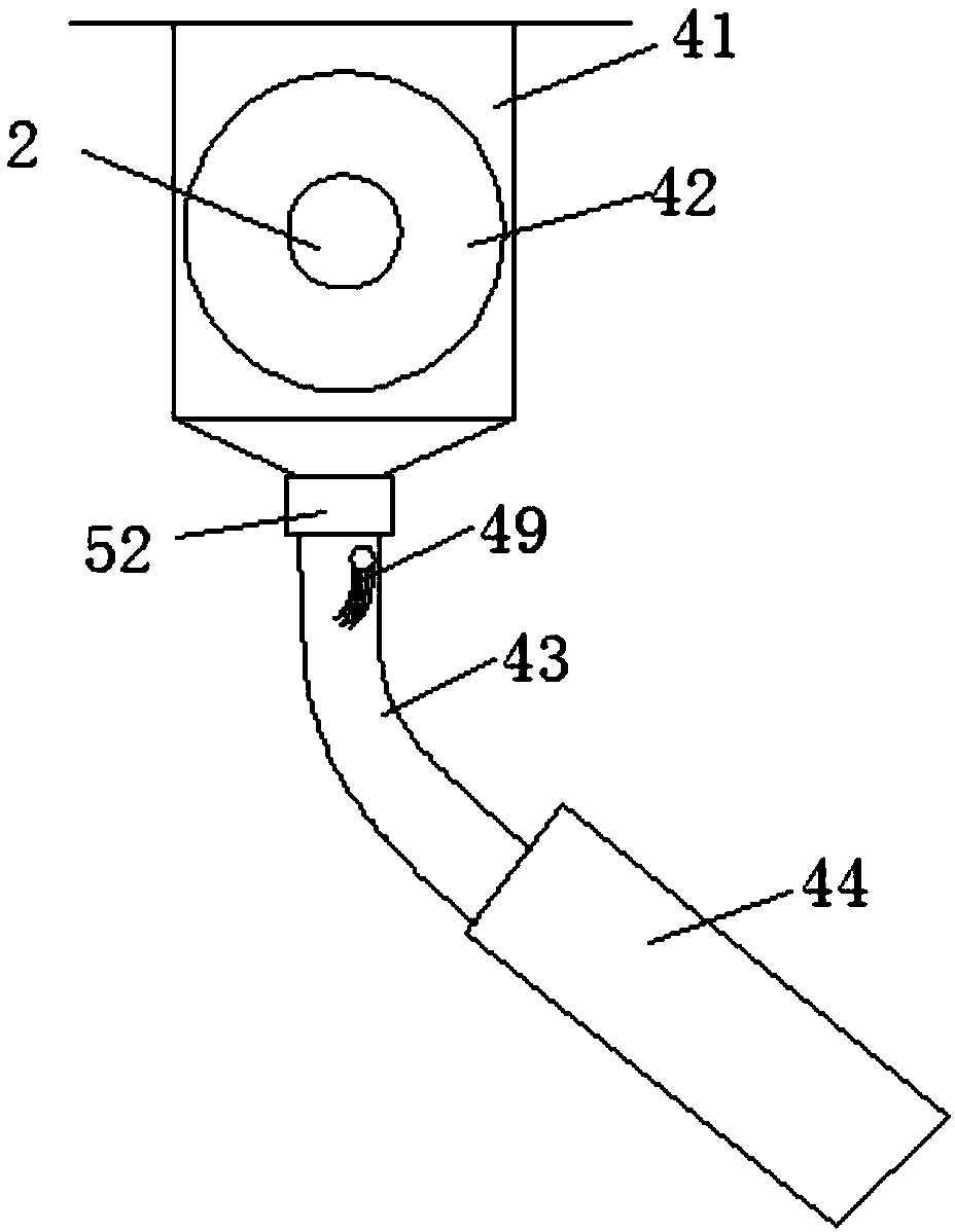
[0023] Such as figure 1 As shown, the fertilizer discharge device for the no-tillage drill includes a fertilizer box 1, a fertilizer discharge shaft 2, a transmission sprocket 3 and a fertilizer discharger 4, and the fertilizer discharge shaft 2 is installed below the fertilizer tank 1, and the fertilizer discharge On the shaft 2, there are several fertilizer dischargers 4 evenly distributed, and the transmission sprocket 3 is fixedly installed on one end of the fertilizer discharge shaft 2, such as figure 2 with 3 As shown, the fertilizer discharger 4 includes a fertilizer discharge box 41, a fertilizer discharge sheave 42, a fertilizer discharge short pipe 43 and a fertilizer discharge ch...


PUM


Abstract

The invention discloses a fertilizer discharge device for a no-tillage drill and a fertilizer discharge device using the fertilizer discharge device, belonging to the field of agricultural machinery, including a fertilizer discharge box, a fertilizer discharge sheave, a short fertilizer discharge pipe and a fertilizer discharge chute. The fertilizer discharge sheave is located inside the fertilizer discharge box; the short fertilizer discharge pipe is fixedly installed at the outlet of the bottom of the fertilizer discharge box and communicates with the inside of the fertilizer discharge box, and the fertilizer discharge chute is composed of a chute The bottom plate is composed of chute side plates located on both sides of the chute bottom plate and having an angle of 90° with the chute bottom plate, and the short fertilizer discharge pipes are located on two surfaces of the chute bottom plate. The beneficial effects of the present invention are: by setting a row of fertilizer slideways under the short fertilizer discharge pipes, the fertilizer coming out of the short fertilizer discharge pipes will slide down slowly on the bottom plate of the chute, and the friction between the fertilizer and the surface of the bottom plate of the chute will To disperse the piled fertilizer to achieve uniform fertilizer discharge.

Description

technical field [0001] The invention relates to the field of agricultural machinery, in particular to a fertilizer discharge device for a no-tillage drill and a fertilizer discharge device using the fertilizer discharge device. Background technique [0002] Efficient fertilization can increase the unit yield of crops and the comprehensive utilization rate of agricultural materials to achieve the purpose of increasing production and income; it can also adjust soil tissue composition, improve plant growth and nutrient absorption. The outer grooved wheel type fertilizer discharge device sets a fertilizer groove in the circumferential direction of the wheel, and the fertilizer is fed from the fertilizer tank into the fertilizer groove through the rotation of the groove wheel, and then falls from the fertilizer groove to the fertilizer guide device to apply the fertilizer to the sowing ground to realize fertilization. However, due to the arrangement of fertilizer troughs on the c...

Claims


Application Information

Patent Timeline
Patent Type & Authority Applications(China)
IPC IPC(8): A01C15/16
CPCA01C15/16
Inventor 简永超冯华安廖斌
Owner 襄阳市弘乾农业机械销售有限公司
Why Eureka
Try Eureka