
Pneumatic uniform fertilizer discharging device
A fertilizer discharge device and pneumatic technology, which is applied in the field of agricultural engineering, can solve the problems of poor fertilizer discharge uniformity, complex structure and high cost, and achieve the effects of convenient control, simple measurement and control system, and simple structure.
- Summary
- Abstract
- Description
- Claims
- Application Information
AI Technical Summary
Problems solved by technology
Method used
Image

Examples
Embodiment Construction
[0028] The present invention will be further described below in conjunction with the accompanying drawings and specific embodiments, but the protection scope of the present invention is not limited thereto.
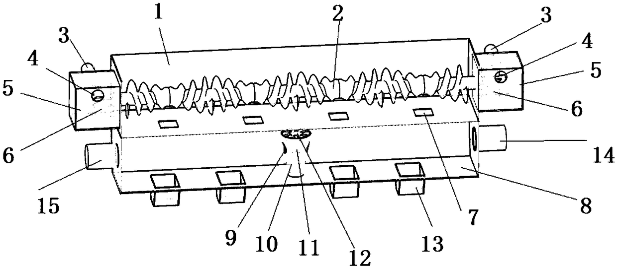
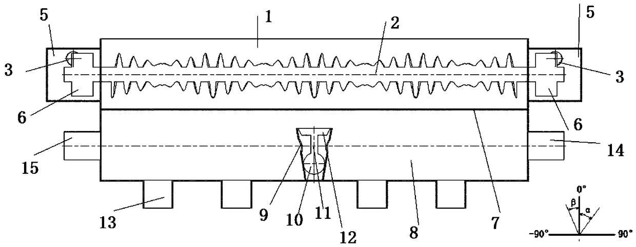
[0029] Such as figure 1 As shown, the pneumatic uniform fertilizer discharge device of the present invention includes an upper fertilizer box 1, a lower fertilizer box 8 and a measurement and control system. The upper fertilizer box 1 is internally provided with a fertilizer discharge shaft 2 that runs through the upper fertilizer box 1. The two ends of the shaft 2 pass through the side wall of the upper fertilizer box 1;
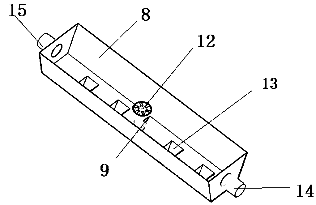
[0030] Such as figure 2 As shown, several fertilizer outlets 13 are set on the bottom surface of the lower fertilizer box 8, and the first tiled air inlet 14 and the second tiled air inlet 15 are arranged at both ends; the first tiled air inlet 14, The second flat air inlet 15 is connected to the air compressor 17 through the first solenoid valve 20...
PUM
 Abstract
Description
Claims
Application Information