Eureka AIR delivers breakthrough ideas for toughest innovation challenges, trusted by R&D personnel around the world.

Fertilizer discharge components of plant protection fertilizer sprayer

A fertilizer spraying and plant protection technology, applied in fertilizer application devices, fertilizer distributors, applications, etc., can solve the problems of inability to control the spreading range, unable to ensure uniform spreading, large fertilizer spreading range, etc., to achieve compact structure, improve quality and effect, The effect of fertilizing evenly

Active Publication Date: 2017-07-07
YINGTIAN AGRI MACHINE TECH TAIZHOU
View PDF5 Cites 0 Cited by
  • Summary
  • Abstract
  • Description
  • Claims
  • Application Information

AI Technical Summary

Problems solved by technology

The power of the walking power machinery is transmitted to the centrifugal throwing structure through the transmission system, and the centrifugal throwing structure is driven to rotate, and the fertilizer is thrown into the farmland in a centrifugal manner. This method can realize mechanical spreading, but the defect is that : The range of centrifugal fertilizer spreading depends on the speed of the walking power machinery. If the speed is fast, the fertilizer spreading range will be large; Spreading range, there is no guarantee of uniform spreading

Method used


Image

  • Fertilizer discharge components of plant protection fertilizer sprayer
  • Fertilizer discharge components of plant protection fertilizer sprayer
  • Fertilizer discharge components of plant protection fertilizer sprayer

Examples


Embodiment Construction

[0031] The present invention will be further described below according to the accompanying drawings and in conjunction with the embodiments.

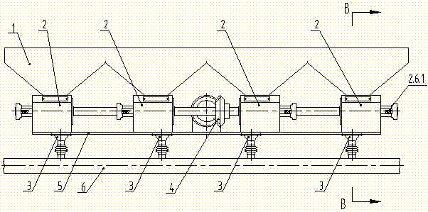
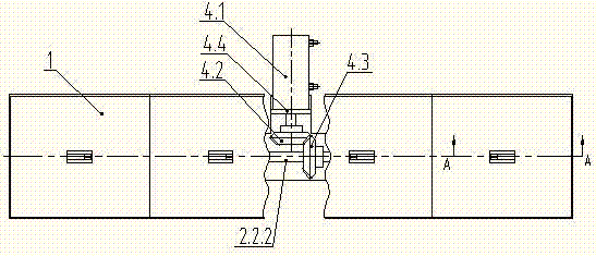
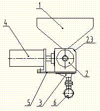
[0032] The fertilizer discharge assembly of the plant protection spray fertilizer machine shown in the accompanying drawings is arranged on the horizontal fertilizer spray pipe 6, and includes a fertilizer storage box 1, 2-6 fertilizer dischargers 2 (4 in this embodiment), 2-6 A material guide cylinder 3 (there are 4 in this embodiment), transmission mechanism 4, support plate 5; support plate 5 is fixedly connected to the front end of the traveling machine; .

[0033] The fertilizer discharge device 2 comprises a fertilizer discharge device housing 2.1, a delivery mechanism 2.2, a retaining brush 2.3, a left bearing sleeve 2.5, and a right support sleeve 2.6; The upper end surface of the support plate 5; the left support shaft sleeve 2.5 and the right support shaft sleeve 2.6 are arranged oppositely, and the left support shaft sleeve ...


PUM


Abstract

The invention discloses a fertilizer discharge assembly of a plant protection fertilizer spraying machine; the fertilizer discharge assembly is arranged on a horizontal fertilizer spraying pipe and includes a fertilizer storage box, a plurality of fertilizer dischargers, a plurality of material guiding barrels, a transmission mechanism and a supporting plate; the supporting plate is fixedly connected at the front of driving machinery; the fertilizer dischargers and the transmission mechanism are supported on the horizontally-arranged supporting plate; the fertilizer dischargers each include a fertilizer discharger shell body, a sending-out mechanism, a blocking brush, a left supporting shaft sleeve and a right supporting shaft sleeve; each sending-out mechanism is arranged in the fertilizer discharger shell body and includes a transmission shaft, a feeding roller and a feeding amount regulating mechanism, and each blocking bush is arranged on the feeding roller; the transmission mechanism is a bevel gear transmission pair driven by a driving motor; the fertilizer storage box is connected above openings at the upper parts of the fertilizer discharger shell bodies, the lower part of the fertilizer storage box is provided with funnel-shaped discharge ports having the same number as the fertilizer dischargers, and the funnel-shaped discharge ports are communicated with the openings at the upper parts of the fertilizer discharger shell bodies. The fertilizer discharge assembly can conveniently and accurately regulate fertilizer discharge amount, discharges fertilizers evenly, and significantly improves the quality and the effect of fertilizer spraying operations.

Description

technical field [0001] The invention relates to the field of agricultural machinery, in particular to a fertilizer discharge assembly of a plant protection fertilizer spraying machine. Background technique [0002] During the growth period of crops, it is necessary to continuously replenish water and spread fertilizers in time to ensure crop yields. Now there are mechanical fertilizer spreaders instead of manual fertilizer spraying operations, which are highly efficient and labor-saving. The existing mechanical fertilizer spreader is arranged on a walking power machine and is provided with a centrifugal throwing structure. The power of the walking power machinery is transmitted to the centrifugal throwing structure through the transmission system, and the centrifugal throwing structure is driven to rotate, and the fertilizer is thrown into the farmland in a centrifugal manner. This method can realize mechanical spreading, but the defect is that : The range of centrifugal f...

Claims


Application Information

Patent Timeline
Patent Type & Authority Patents(China)
IPC IPC(8): A01C15/12
Inventor 曹冬林史志中唐莉莉吴小伟翟步顺王荣
Owner YINGTIAN AGRI MACHINE TECH TAIZHOU
Why Eureka
Eureka Blog
Learn More