Mortar stirring cylinder

A mortar mixing and cylinder technology, which is applied to mixer accessories, dissolving, mixers, etc., can solve the problems of poor mixing effect of the sandbox mixing cylinder and the solidification of mortar on the inner wall of the cylinder, so as to avoid cleaning difficulties and improve the utilization of mortar. High rate, full mixing effect

Inactive Publication Date: 2018-04-13
CHONGQING RUIXUAN HAOBANG NEW BUILDING MATERIAL
View PDF4 Cites 3 Cited by
  • Summary
  • Abstract
  • Description
  • Claims
  • Application Information

AI Technical Summary

Problems solved by technology

[0005] The purpose of the present invention is to provide a mortar mixing tank to solve the problems that the existing sand box mixing tank has poor mixing effect and the mortar may solidify on the inner wall of the tank

Method used


Image

  • Mortar stirring cylinder
  • Mortar stirring cylinder
  • Mortar stirring cylinder

Examples


Embodiment Construction

[0033] The following is further described in detail through specific implementation methods:

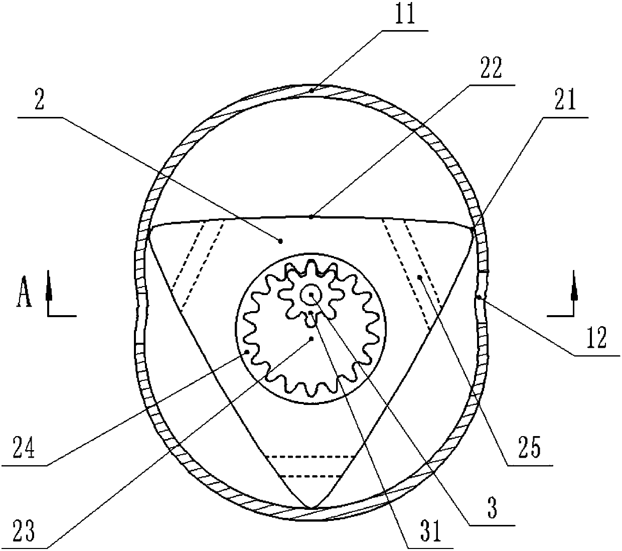
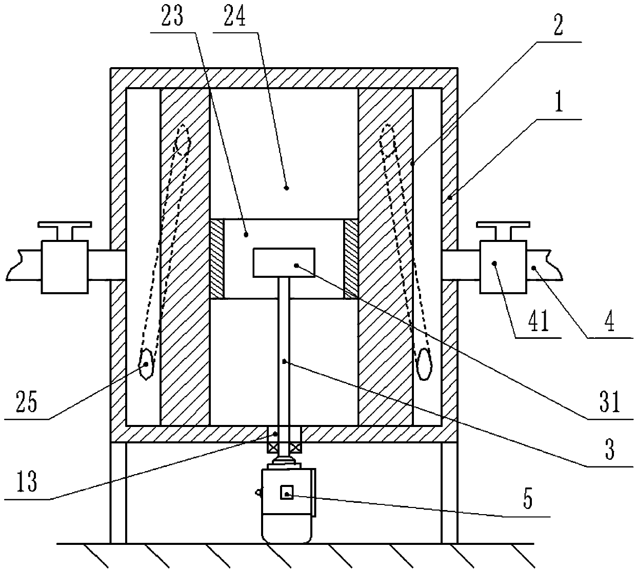
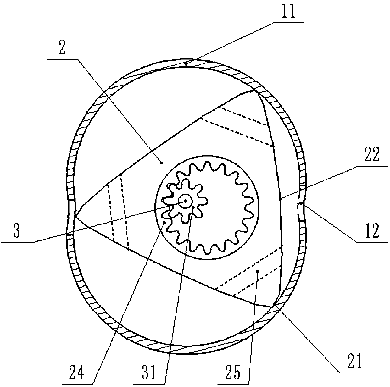
[0034] The reference signs in the drawings of the specification include: cylinder block 1, circular arc portion 11, thin waist portion 12, first through hole 13, triangular rotor 2, side edge 21, side surface 22, second through hole 23, inner ring gear 24, the communication channel 25, the rotating shaft 3, the gear 31, the discharge pipe 4, the valve 41, and the rotating motor 5.

[0035] like figure 1 and figure 2 The mortar mixing cylinder shown includes a cylinder body 1, a triangular rotor 2 and a rotating shaft 3. The top wall of the cylinder body 1 is a flat top, the bottom wall of the cylinder wall is a flat bottom, the side wall of the cylinder body 1 is in the shape of an "8", and the side wall of the cylinder body 1 includes two arc parts 11 and two thin waist parts 12 , The two thin waists 12 are connected with a discharge pipe 4, and the discharge pipe 4 is provided ...


PUM


Abstract

The invention relates to the technical field of mortar stirring equipment and particularly discloses a mortar stirring cylinder, comprising a cylinder body, a triangular rotor and a spindle; the cylinder body is a cycloidal cylinder body, the top wall of the cylinder body is a flat top, the bottom wall of the cylinder body is a flat bottom, the sidewall of the cylinder body is in figure-eight shape, the sidewall of the cylinder body includes two arc portions and two thin-waist portions, a discharge pipe is communicated with the thin-waist portions, the cylinder body is provided with a first through hole that is arranged in the center of the cylinder body, and the triangular rotor is in triangular prism shape, is positioned in the cylinder body and is rotationally connected with the cylinder body. The invention is intended to solve the problems that the stirring cylinder of an existing mortar tank is poor in mixing effect and mortar may consolidate on the inner wall of the cylinder body.

Description

technical field [0001] This patent relates to the technical field of mortar mixing equipment. Background technique [0002] Most of the existing mortar mixing devices use mixing blades. The Chinese patent document whose publication number is CN102729334A discloses a mortar stirring device, comprising: a cylinder; a cover plate arranged on the top of the cylinder; a main shaft, which passes through the cover plate and extends into the cylinder, and the main shaft The end is connected with a number of stirring blades; the driving device is connected to the reducer and the main shaft in turn; the mortar stirring device also includes an air stirring unit, and the air stirring unit includes an air pump, an air pipeline, and an air pump connected to the air. The valve of the pipeline, the air pipeline extends vertically downward along the outer wall of the cylinder and penetrates into the cylinder, and the air pump and valve are arranged above the cover plate. [0003] In the ab...

Claims


Application Information

Patent Timeline
IPC IPC(8): B01F13/10B01F15/00B01F15/02
CPCB01F33/82B01F35/30B01F35/7176B01F35/7543
Inventor 齐业信
Owner CHONGQING RUIXUAN HAOBANG NEW BUILDING MATERIAL
Why Eureka
Try Eureka