Serration spindle driving system for electric saw

A technology of spindle drive and sawtooth, which is applied in the direction of metal sawing equipment, tool manufacturing of sawing machine devices, metal processing equipment, etc., can solve the problems of not meeting the precision requirements, not very high precision, and inconvenient, etc., to achieve protection in and out The effect of oil circuit, clear organization and simple structure

Inactive Publication Date: 2018-04-13
如皋千骏工具有限公司
View PDF5 Cites 0 Cited by
  • Summary
  • Abstract
  • Description
  • Claims
  • Application Information

AI Technical Summary

Problems solved by technology

However, the saw teeth used in traditional saws have the following disadvantages: For the spindle with the tool installed, the spindle needs to perform different actions according to the requirements of the processed parts. Generally, only the spindle needs to move up and down. However, when processing threads, the main shaft needs to be rotated. In this case, it is necessary to install motors, drive shafts and other components on the original basis. Therefore, it is necessary to replace the drive sliders and other components installed on the main shaft, which is very troublesome. ;For its gantry structure, due to aesthetics, safety and other considerations, the lines will be gathered together and stored in the gantry structure, so the gantry structure will be made hollow, so as to facilitate the storage of lines and other components, and at the same time the front end of the gantry structure It will connect the main shaft and the drive structure that drives the main shaft, so there are certain requirements for the strength of the gantry structure; in addition, when putting the circuit into the gantry structure, it needs to be put in from the bottom of the gantry structure, which is not convenient; for The drive mechanism that drives the spark machine to reciprocate up and down often uses a drive cylinder to drive the slider to move up and down. However, the precision of this structure is not very high. For some products that require high precision, this drive mechanism cannot achieve to the accuracy requirement

Method used


Image

  • Serration spindle driving system for electric saw
  • Serration spindle driving system for electric saw
  • Serration spindle driving system for electric saw

Examples


Embodiment Construction

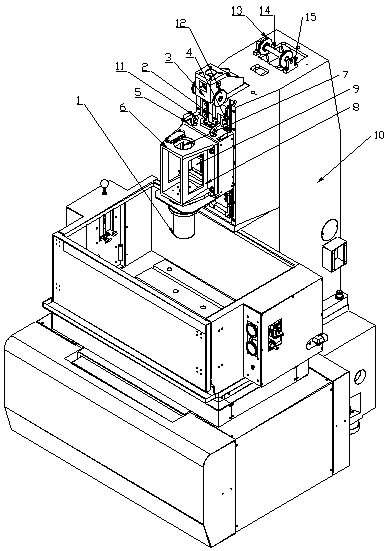
[0031] Such as figure 1 From the schematic diagram shown, it can be seen that the saw tooth for the electric saw of the present invention includes a main shaft, a driving slider, a driving guide rail, a proximity switch and a gantry frame.

[0032] Drive guide rail 4 has a pair, is symmetrically installed on the side wall of gantry 10, and the two ends of drive slide block 5 are respectively installed on two drive guide rails 4, and can be driven by drive unit and move up and down.

[0033] In the present invention, the driving device has two types of driving. The first driving device is a linear motor, which is installed on the gantry 10 and whose lower end is connected with the driving slider 5 .

[0034] The second kind of driving device is a driving screw 2, the upper end of the driving screw 2 is connected with the driving motor, and can be driven by the driving motor to rotate, the driving motor is installed on the upper end of the gantry 10 through the mounting base 3, ...


PUM


Abstract

The invention relates to a serration spindle driving system for an electric saw. The serration spindle driving system for the electric saw includes a spindle, a driving sliding block, driving guidingrails, a proximity switch and a portal frame; the driving guiding rails are two and are symmetrically arranged at the side wall of the portal frame, two ends of the driving sliding block are separately arranged at two driving guiding rails to move up and down driven by a driving device, and the driving sliding block and the spindle are connected with a transition piece; and the proximity switch isarranged at the side end of the driving sliding block, meanwhile the portal frame is provided with a contact plate which is matched with the proximity switch, the side end of the portal frame is provided with a scale plate, and the contact plate can be regulated up and down according to the scale plate. The serration spindle driving system for the electric saw has the advantages that the serration spindle driving system for the electric saw can offer foundation for precisely controlling working operation of the spindle, and can meet the spindle rotating requirement without replacing components.

Description

technical field [0001] The invention relates to an electric tool, in particular to a sawtooth spindle driving system for an electric saw. Background technique [0002] Chainsaw, also known as "power saw", was invented by German Andreas. Invented by Steele in 1926, it greatly saves the time and labor spent on cutting materials. A chainsaw is powered by electricity and is a cutting tool used to cut wood, stone, steel, etc., with sharp teeth on the edge. Separate fixed and portable, the saw blade is generally made of tool steel, there are round, strip and chain and so on. [0003] At present, in the process of processing the circular saw blade, a spark machine is used for the processing of its planar structure. However, the saw teeth used in traditional saws have the following disadvantages: For the spindle with the tool installed, the spindle needs to perform different actions according to the requirements of the processed parts. Generally, only the spindle needs to move up...

Claims


Application Information

Patent Timeline
Patent Type & Authority Applications(China)
IPC IPC(8): B23D65/00B23H1/00
CPCB23D65/00B23H1/00
Inventor 吴宏
Owner 如皋千骏工具有限公司
Why Eureka
Try Eureka