
High-altitude balloon tearing system and high-altitude balloon tearing method of high-altitude balloon tearing system

A high-altitude balloon and tearing rope technology is applied in the field of adjacent space to achieve the effects of large load capacity, simple structure, and improved system safety and reliability.

Inactive Publication Date: 2018-04-13
NAT UNIV OF DEFENSE TECH
View PDF9 Cites 9 Cited by
  • Summary
  • Abstract
  • Description
  • Claims
  • Application Information

AI Technical Summary

Problems solved by technology

[0004] At present, the existing high-altitude balloons are naturally blasted after the ball umbrella is separated (continue to rise to a certain height, overpressure blasting). literature

Method used


Image

  • High-altitude balloon tearing system and high-altitude balloon tearing method of high-altitude balloon tearing system
  • High-altitude balloon tearing system and high-altitude balloon tearing method of high-altitude balloon tearing system
  • High-altitude balloon tearing system and high-altitude balloon tearing method of high-altitude balloon tearing system

Examples


Embodiment 1

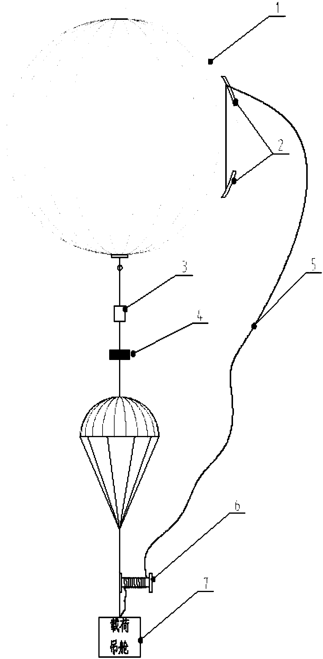
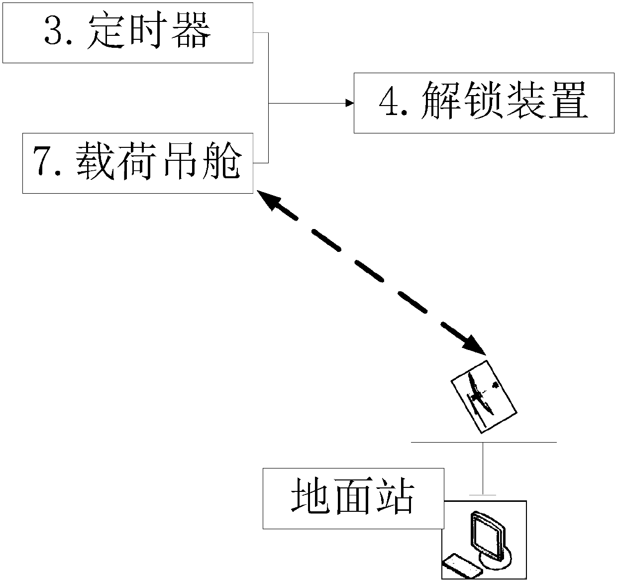
[0041] A high-altitude balloon fixed-height tearing system, which includes a high-altitude balloon body 1, a small hole 8, a tearing width 2, a tearing rope 5, a main load-bearing rope 9, a load pod 7, an unlocking device 4, and a rope winder 6 , timer 3, ground station, height sensor and satellite signal module;

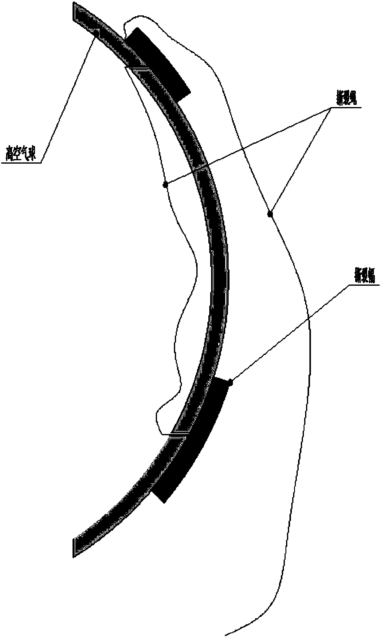
[0042] The small hole 1 is arranged on the surface of the high-altitude balloon body 1 for pre-embedding the tear rope 5; the tear web 2 is a sheet of material attached to the small hole 8 on the outer surface of the high-altitude balloon body 1. Adhesive bonding or thermocompression bonding is applied to the position of the small hole on the surface of the high-altitude balloon body 1 for fixing the tearing rope 5 and sealing the small hole 8; one end of the tearing rope 5 passes through a small hole into the high-altitude The balloon body 1 is fixed in the small hole or at the junction of the tear web and the high-altitude balloon body 1; the other end passes thro...

Embodiment 2

[0052] A high-altitude balloon fixed height tearing method, it utilizes the high-altitude balloon fixed height tearing system of embodiment 1, comprises the following steps:

[0053] S1. Connect and fix the various parts of the system, wrap the excess tearing rope 5 on the rope winder 6, so that the length of the free part is greater than the length of the main load-bearing rope 9, so as to avoid the tearing rope 5 being damaged during the ascent of the system. force to destroy high-altitude balloons;

[0054] S2. Use the inflated high-altitude balloon body 1 to carry the load pod 7 to a predetermined height to perform a predetermined task;

[0055] S3. After the task is completed, the unlocking device 4 is triggered to separate the load pod 7 from the high-altitude balloon body 1 by triggering the timer 3 and / or issuing an unlocking command at a specified height by the ground station; when the timer 3 and the ground station issue an unlocking at the same time command, the pr...


PUM


Abstract

A high-altitude balloon tearing system comprises a high-altitude balloon body (1), small holes (8), tearing patches (2), a tearing rope (5), a main force bearing rope (9), a load nacelle (7) and an unlocking device (4). The two small holes (8) and the two tearing patches (2) are separately formed in the surface of the high-altitude balloon body (1) in the radial direction, and the tearing patches(2) are used for fixing the tearing rope (5) and sealing the small holes (8). One end of the tearing rope (5) penetrates into the high-altitude balloon body (1) through one small hole and is fixed into the corresponding small hole or fixed to the combination position of the corresponding tearing patch and the high-altitude balloon body (1); and the other end of the tearing rope (5) penetrates outof the other small hole and is guided out along the upper end of the combination position of the corresponding tearing patch (2) and the high-altitude balloon body (1) and fixed to the load nacelle (7) finally. When the high-altitude balloon body (1) is separated from the load nacelle (7), the load nacelle (7) descends perpendicularly to drive the tearing rope (5) to tear the high-altitude balloonbody (1) apart.

Description

technical field [0001] The invention belongs to the technical field of near space, and relates to a system and a method for setting and tearing a high-altitude balloon. Background technique [0002] Near space is an emerging strategic space that bridges aviation and aerospace. The development of near space vehicles, access to and use of near space is of great significance for my country to build an all-round and three-dimensional security system. [0003] High-altitude balloons are mainly used to carry sounding instruments to high altitudes for the detection of meteorological elements such as temperature, pressure, humidity, and wind. They can also carry equipment to complete tasks such as signal relay, scientific experiments, and military monitoring. High-altitude balloons are an important tool for studying the stratosphere, especially for the development of meteorology and the design of high-altitude aircraft. [0004] At present, the existing high-altitude balloons are n...

Claims


Application Information

Patent Timeline
Patent Type & Authority Applications(China)
IPC IPC(8): B64B1/40
CPCB64B1/40
Inventor 杨希祥张家实邓小龙麻震宇侯中喜
Owner NAT UNIV OF DEFENSE TECH
Learn More