Separating device of booster for aircraft

A separation device and aircraft technology, applied in the field of aircraft, can solve the problems of complex installation structure, long time-consuming installation and separation, etc., and achieve the effect of reliable connection

Active Publication Date: 2018-04-13
阳森供应链管理(日照)有限公司
View PDF6 Cites 2 Cited by
  • Summary
  • Abstract
  • Description
  • Claims
  • Application Information

AI Technical Summary

Problems solved by technology

[0003] The installation structure of existing boosters for aircraft is complicated, and it takes a long time to install and separate

Method used


Image

  • Separating device of booster for aircraft
  • Separating device of booster for aircraft
  • Separating device of booster for aircraft

Examples


Embodiment

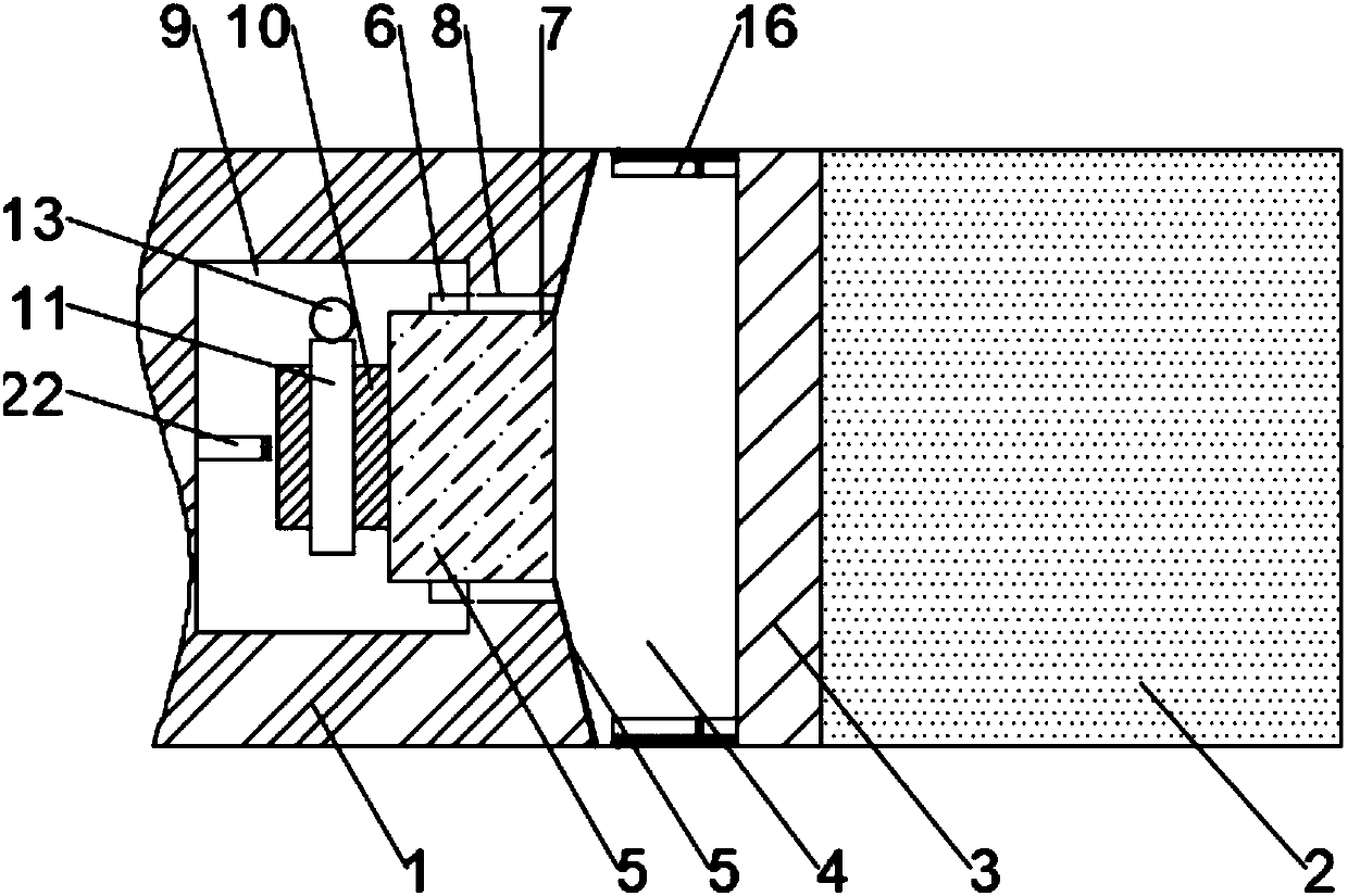
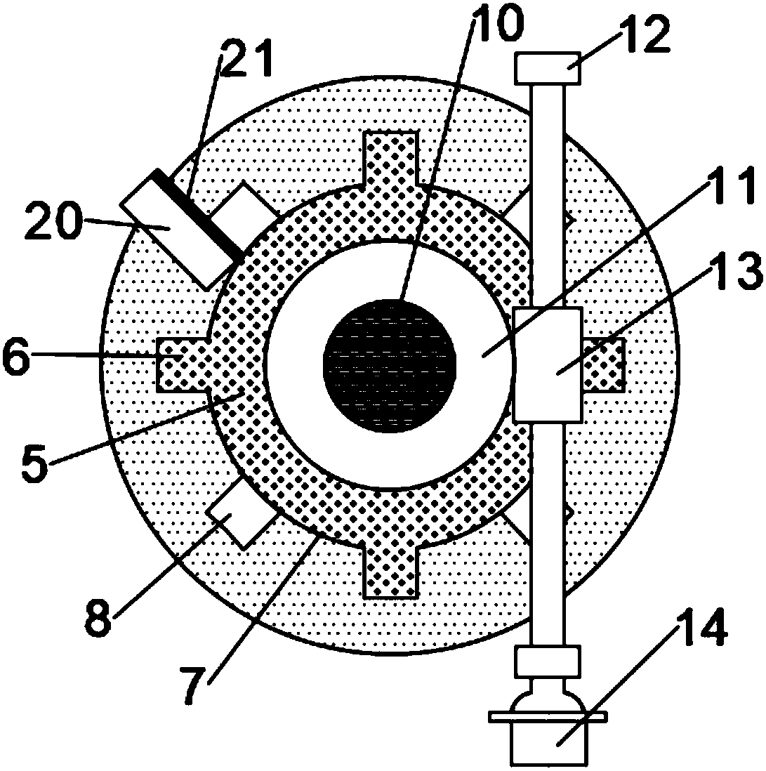
[0025] Such as figure 1 and figure 2 As shown, the present invention provides a separation device for an aircraft booster, comprising an aircraft body 1 and a booster 2 arranged behind the aircraft body 1, the front end of the booster 2 is provided with a separation mount 3, The front end of the separation mount 3 is equipped with a separator 4, the front end of the separator 4 is provided with a connecting column 5, and the side of the connecting column 5 is evenly provided with four clamping plates 6 along the circumference, and the main body of the aircraft 1 The rear end of the connecting hole 7 is provided with a connecting hole 7, and the connecting hole 7 is provided with four slots 8 corresponding to the clamping plate 6, and the containing cavity 9 is provided with a limit plate 20, when the clamping plate 6 on the rotating shaft 10 rotates When the clamping groove 8 is at the position, the clamping plate 6 is in contact with the limiting plate 20, and the surface o...


PUM


Abstract

The invention discloses a separating device of a booster for an aircraft. The separating device comprises an aircraft main body and a booster arranged behind the aircraft main body, wherein a separating and mounting seat is arranged at the front end of the booster; a separator is mounted at the front end of the separating and mounting seat; a connecting column is arranged at the front end of the separator; four clamping plates are uniformly arranged on the side surface of the connecting column in the circumferential direction; a connecting hole is formed in the rear end of the aircraft main body; four clamping grooves which respectively correspond to the clamping plates are formed in the connecting hole; an accommodating cavity is formed in the front end of the connecting hole; a rotatingshaft is arranged at the center of the front end of the connecting column; a worm gear is arranged on the rotating shaft; a worm is arranged in the accommodating cavity through a worm bracket; the worm is meshed with the worm gear; a worm motor is arranged at one end of the worm; a separating air cylinder is arranged in the accommodating cavity; and the output end of the separating air cylinder directly faces the center of the rotating shaft. According to the separating device disclosed by the invention, the connection between the booster and the aircraft is reliable; and the mounting and theseparating are high-efficiency and convenient.

Description

technical field [0001] The invention relates to the field of aircraft technology, in particular to a separation device for an aircraft booster. Background technique [0002] A flight vehicle is a device that flies in the atmosphere or in the space outside the atmosphere (space). Aircraft are divided into 3 categories: aircraft, spacecraft, rockets and missiles. Those flying in the atmosphere are called aircraft, such as balloons, airships, airplanes, etc. They rely on the static buoyancy of the air or the aerodynamic force generated by the relative motion of the air to lift into the air. Those flying in space are called spacecraft, such as artificial earth satellites, manned spacecraft, space probes, and space shuttles. Driven by the launch vehicle, they gain the necessary speed to enter space, and then rely on inertia to make orbital motion similar to celestial bodies. [0003] The installation structure of the existing booster for aircraft is complicated, and it takes ...

Claims


Application Information

Patent Timeline
Patent Type & Authority Applications(China)
IPC IPC(8): B64G1/64
CPCB64G1/645
Inventor 李杨宇
Owner 阳森供应链管理(日照)有限公司
Why Eureka
Try Eureka