A prefabricated beam and prefabricated column connection structure and construction method

A technology for connecting structures and assembling columns, which is applied in the direction of building construction and construction, and can solve problems such as dense arrangement of steel bars at the lower part of beams, difficulty in construction, difficulty in pouring concrete, and loss of bearing capacity of concrete nodes. Effects of shear resistance, impact reduction, and improved seismic performance

Active Publication Date: 2019-05-10
NANCHANG HANGKONG UNIVERSITY
View PDF4 Cites 0 Cited by
  • Summary
  • Abstract
  • Description
  • Claims
  • Application Information

AI Technical Summary

Problems solved by technology

[0003] There is a prefabricated concrete frame structure node connection, which is characterized in that the beams and columns are prefabricated separately, the floor slab and the core area of ​​the node are cast-in-place, and the steel bars at the lower part of the beam are anchored by straight lines, bends or mechanical anchors, but the disadvantage of this node is that the lower part of the beam The steel bars are densely arranged in the core area of ​​the joint, and the construction is difficult. At the same time, due to the dense distribution of reinforcement in the core area of ​​the joint, it is difficult to fully vibrate and compact the poured concrete
A new type of prefabricated concrete frame structure joint connection, which is characterized in that the joints adopt the prefabricated joints designed by the corbels. There is a partial pressure phenomenon in the corbel, which causes the concrete to be partially crushed and the node loses its bearing capacity
[0004] In summary, some existing prefabricated beam-column joint connection methods have achieved good results under suitable working conditions, but there are still specific problems to be solved, such as the improvement of joint connection strength, improvement of seismic performance, and improvement of construction efficiency.

Method used


Image

  • A prefabricated beam and prefabricated column connection structure and construction method
  • A prefabricated beam and prefabricated column connection structure and construction method
  • A prefabricated beam and prefabricated column connection structure and construction method

Examples


Embodiment Construction

[0036] The embodiments of the present invention will be described in further detail below in conjunction with the accompanying drawings, but the present embodiments are not intended to limit the present invention, and any similar structures and similar changes of the present invention should be included in the protection scope of the present invention.

[0037] The design and construction technical requirements of the upper assembly column and the lower assembly column, the design and construction technical requirements of the assembly beam, the on-site welding construction technical requirements, the post-cast concrete design and construction technical requirements, the interface bonding layer laying construction technical requirements, etc. The description will not be repeated in the implementation manner, and the implementation manner related to the structure of the present invention will be focused on.

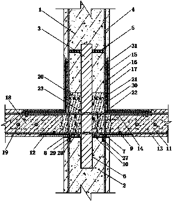
[0038] figure 1 It is a schematic cross-sectional view of the connect...


PUM


Abstract

The invention relates to a connection structure between an assembled beam and an assembled column, which is characterized in that a connecting steel body is arranged between an upper assembly column and a lower assembly column, and a connection steel body insertion groove is arranged on the lower assembly column; Set the column top reinforcement plate and joint shock-absorbing layer on the surface, and set vertical connecting ribs on the column top reinforcement plate; preset the beam bottom reinforcement plate at the junction of the lower surface of the assembled beam and the lower assembly column; assemble Reinforcement gussets, interface bonding layer, and mortar protection layer are set in sequence in the reinforcing body layout groove at the junction of the upper surface of the beam and the upper assembly column; a connecting steel plate is installed between two adjacent assembly beams; The post-cast concrete is filled in the gap at the intersection of the assembly column and the assembly beam, and the horizontal and vertical hoops are set. The invention can not only improve the connection strength and stress properties of the assembled beam-column joint, but also reduce the difficulty of on-site assembly construction. The invention also discloses a construction method for the connection structure between the assembled beam and the assembled column.

Description

technical field [0001] The invention relates to a prefabricated building structure, in particular to a prefabricated beam and prefabricated column connection structure and a construction method that can effectively improve the stress performance and earthquake resistance of beam-column joints and improve on-site construction efficiency, belonging to the field of construction engineering. Background technique [0002] In recent years, with the rapid development of my country's economy, the industrialization of construction has been continuously developed. The prefabricated concrete structure is an important structure to realize the development mode of industrialization of construction. Its advantages of economy, convenience and environmental protection have been highly praised at home and abroad. big concern. In current engineering, prefabricated structural connections are mainly divided into wet connection and dry connection. Wet connection is the connection form of pouring p...

Claims


Application Information

Patent Timeline
Patent Type & Authority Patents(China)
IPC IPC(8): E04B1/21
CPCE04B1/21E04B1/215
Inventor 韩尚宇谢洪阳张慧华王中华陈家燊严浩李凯仁
Owner NANCHANG HANGKONG UNIVERSITY
Why Eureka
Try Eureka