A control method and system of a space optical remote sensor based on geomagnetic latitude

A space optical remote sensing and latitude technology, which is applied in the field of aerospace optical remote sensor control, can solve the problems of large amount of injected command data, failure to capture the target position, and low data transmission rate

Inactive Publication Date: 2019-12-24
CHANGCHUN INST OF OPTICS FINE MECHANICS & PHYSICS CHINESE ACAD OF SCI
View PDF3 Cites 0 Cited by
  • Summary
  • Abstract
  • Description
  • Claims
  • Application Information

AI Technical Summary

Problems solved by technology

[0004] The disadvantages of controlling the working mode and mode conversion of aerospace optical remote sensors based on the flight time in orbit are: more ground participation, unable to realize automatic control of working mode and automatic mode conversion, and low efficiency; The limitation of the data transmission link, that is, the data transmission rate between the sky-ground link is low, and the transmission time for the injection command with a large amount of data is long, and the transmission of the injection command needs to be started a long time in advance; due to the start of the ground estimated working mode There may be errors in the on-orbit flight time of , end and working mode switching, which will affect the accuracy of the working mode and mode switching control. A large amount of redundant image data, if the estimated on-orbit flight time is delayed, the target position will not be captured

Method used


Image

  • A control method and system of a space optical remote sensor based on geomagnetic latitude
  • A control method and system of a space optical remote sensor based on geomagnetic latitude
  • A control method and system of a space optical remote sensor based on geomagnetic latitude

Examples


Embodiment Construction

[0053] The technical solutions in the embodiments of the present invention will be clearly and completely described below with reference to the accompanying drawings in the embodiments of the present invention. Obviously, the described embodiments are only a part of the embodiments of the present invention, but not all of the embodiments. Based on the embodiments of the present invention, all other embodiments obtained by those of ordinary skill in the art without creative efforts shall fall within the protection scope of the present invention.

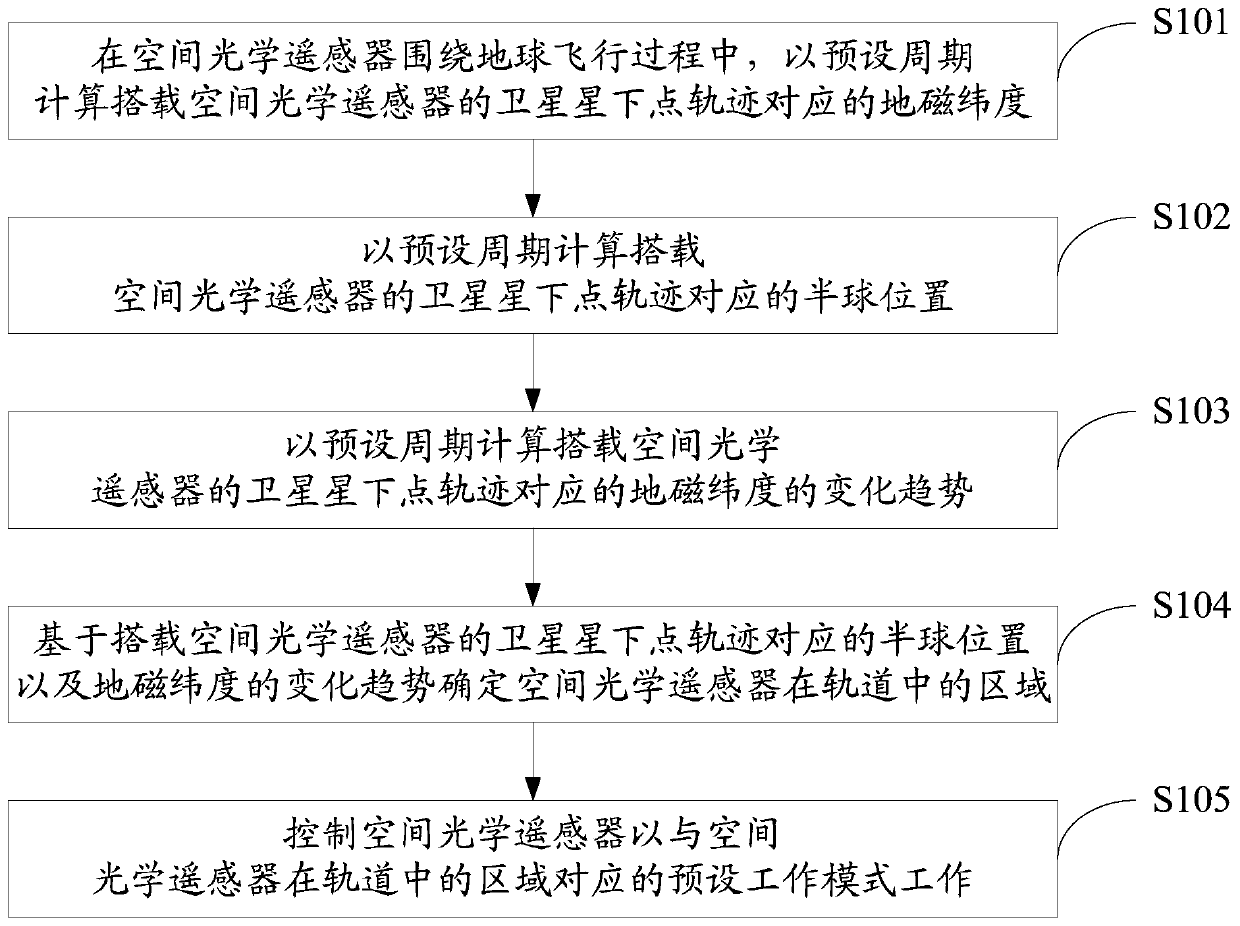
[0054] like figure 1 As shown, it is a flowchart of Embodiment 1 of a method for controlling a geomagnetic latitude-based space optical remote sensor disclosed in the present invention, and the method includes:

[0055] S101. During the flight of the space optical remote sensor around the earth, calculate the geomagnetic latitude corresponding to the sub-satellite point trajectory of the satellite carrying the space optical remote sen...


PUM


Abstract

The present invention provides a control method for a space optical remote sensor based on geomagnetic latitude, including: calculating the geomagnetic latitude corresponding to the sub-satellite track of a satellite equipped with a space optical remote sensor in a preset period; calculating the sub-satellite track of a satellite in a preset period Corresponding hemispherical position; Calculate the change trend of the geomagnetic latitude corresponding to the sub-satellite point trajectory of the satellite equipped with the space optical remote sensor at a preset period; based on the hemispheric position and the change of the geomagnetic latitude corresponding to the sub-satellite point trajectory of the satellite equipped with the space optical remote sensor The trend determines the area of ​​the space optical remote sensor in orbit; the space optical remote sensor is controlled to work in a preset working mode corresponding to the area of ​​the space optical remote sensor in orbit. The invention can automatically control the working mode of the optical remote sensor according to the corresponding geomagnetic latitude during the orbital flight of the optical remote sensor around the earth. The invention also discloses a control system of the space optical remote sensor based on the geomagnetic latitude.

Description

technical field [0001] The invention relates to the technical field of control of space optical remote sensors, in particular to a control method and system of a space optical remote sensor based on geomagnetic latitude. Background technique [0002] Each aerospace optical remote sensor has different working modes and mode transitions during orbit around the earth according to its own mission. Most of the working modes and mode transitions are related to the position of the earth. Calibration and shooting, etc. [0003] In the past, the working mode and mode switching of the aerospace optical remote sensor were controlled based on the on-orbit flight time, that is, the ground estimated the on-orbit flight time of the start, end and working mode switching, and then sent the injection command from the ground to the aerospace optical remote sensor. The aerospace optical remote sensor completes the specified working mode and mode conversion control at the specified on-orbit fli...

Claims


Application Information

Patent Timeline
Patent Type & Authority Patents(China)
IPC IPC(8): G01C11/02
CPCG01C11/02
Inventor 于涛宋克非宋元章
Owner CHANGCHUN INST OF OPTICS FINE MECHANICS & PHYSICS CHINESE ACAD OF SCI
Why Eureka
Try Eureka