Check patentability & draft patents in minutes with Patsnap Eureka AI!

Driving method and driving circuit of selectable driving tube work area

A technology of working area and driving method, applied in instruments, static indicators, etc., can solve the problems of inconsistent driving current, poor low gray-scale uniformity, poor display uniformity, etc., to improve brightness uniformity, optimize display effect, and high uniformity. sexual effect

Active Publication Date: 2018-04-13
CHENGDU JINGSHA TECH
View PDF9 Cites 15 Cited by
  • Summary
  • Abstract
  • Description
  • Claims
  • Application Information

AI Technical Summary

Problems solved by technology

like figure 1 As shown, due to fluctuations in the MOS tube process or TFT process, the characteristics of different drive transistors are inconsistent, and there will be some differences in I_V curve characteristics during use, resulting in inconsistency in the drive current, especially in the small current region (the range of the current region is I1 -I2), resulting in poor display uniformity, and the low grayscale uniformity corresponding to the small current is even worse, resulting in a decrease in the uniformity of the entire display and a reduction in the display effect.
In existing inventions, there is a pixel circuit structure that compensates threshold voltage drift, but usually requires many transistors to build circuits and relatively complicated external signal drive methods, which is not conducive to the production of high PPI displays.

Method used


Image

  • Driving method and driving circuit of selectable driving tube work area
  • Driving method and driving circuit of selectable driving tube work area
  • Driving method and driving circuit of selectable driving tube work area

Examples


Embodiment Construction

[0032] The technical solutions claimed by the present invention will be described in further detail in conjunction with the accompanying drawings.

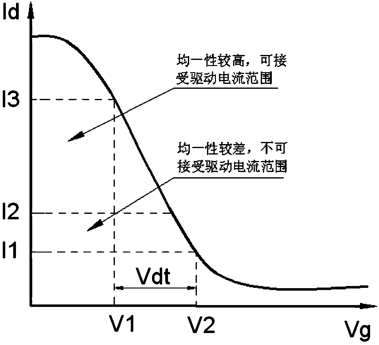
[0033] Those skilled in the art should understand that under the same display brightness, in order to bring the overall brightness effect to the human eye to remain unchanged, the less the light-emitting time in one frame, the greater the required light-emitting brightness, that is, it is required to drive the light-emitting current The larger the , the longer the light-emitting time in one frame, and the smaller the required light-emitting brightness, that is, the smaller the driving light-emitting current is required.

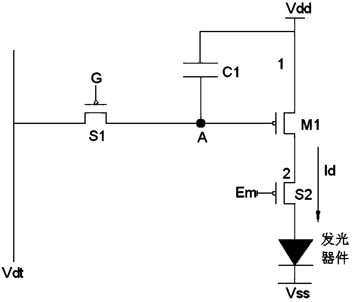
[0034] The technical solution claimed in this application includes a driving method for selectively driving the working area of ​​the tube and a driving circuit for selectively driving the working area of ​​the tube. The following are examples to illustrate, in the common circuits of active pixel driving circuits...


PUM


Abstract

The invention discloses a driving method and a driving circuit of a selectable driving tube work area. In an active pixel driving circuit, a switch is added to adjust the time length of light emittingof a light emitting device in one frame, on the condition that the required light emitting brightness is ensured to be constant, the required current work area range of a driving tube is I2-I4, uniformity of brightness of the light emitting device in a display is improved, and the display effect is optimized.

Description

technical field [0001] The invention relates to a display method and a driving circuit, in particular to a driving method capable of selecting the working area of ​​the driving tube and a driving circuit capable of selecting the working area of ​​the driving tube. Background technique [0002] OLED, LED, QLED, Micro-OLED / LED and other active light-emitting display devices are composed of pixel arrays, and each pixel contains several sub-pixels. The common ones are RGB system and RGBW system. In the RGB system, each pixel contains a red sub-pixel, a green sub-pixel, and a blue sub-pixel; in the RGBW system, each pixel contains a red sub-pixel, a green sub-pixel, a blue sub-pixel, and a white sub-pixel sub-pixel. Effectively control the brightness of each sub-pixel of the pixel unit to achieve the required display color. [0003] Different from liquid crystal displays (LCDs), autonomous light-emitting displays have advantages such as thinness, high brightness, and high contr...

Claims


Application Information

Patent Timeline
Patent Type & Authority Applications(China)
IPC IPC(8): G09G3/3233G09G3/32
CPCG09G3/32G09G3/3233
Inventor 吴素华黎守新余有勇候珊珊
Owner CHENGDU JINGSHA TECH
Features
  • R&D
  • Intellectual Property
  • Life Sciences
  • Materials
  • Tech Scout
  • Unparalleled Data Quality
  • Higher Quality Content
  • 60% Fewer Hallucinations
Learn More