Infrared camera having dust collection structure
An infrared camera and its own technology, applied in the field of infrared cameras, can solve problems such as the camera not working normally, and achieve the effect of less impact on blind areas of sight and easy cleaning.
- Summary
- Abstract
- Description
- Claims
- Application Information
AI Technical Summary
Problems solved by technology
Method used
Image
Examples
Embodiment 1
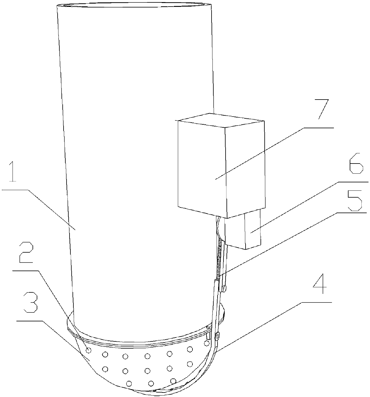
[0024] like figure 1 As shown, a synchronously driven dust collection device for an infrared camera includes a body 1, the end of the body 1 is provided with a plurality of cameras 2 distributed in a spherical shape, and the end of the body 1 is also provided with a sealing cover for the plurality of cameras 2 The spherical glass cover 3 is provided with a dust suction structure moving outside the outer surface of the spherical glass cover 3 .
[0025] In this embodiment, the infrared camera is consistent with the existing infrared camera, the internal structure is not changed, and the spherical glass cover 3 that will seal and cover several cameras 2 is directly arranged outside the camera 2, so as to prevent dust from falling on each camera 2 independently. Clean up one by one to reduce the difficulty of cleaning; secondly, a dust suction structure is arranged outside the spherical glass cover 3 to regularly remove the dust on the surface of the dust suction structure, and t...
Embodiment 2
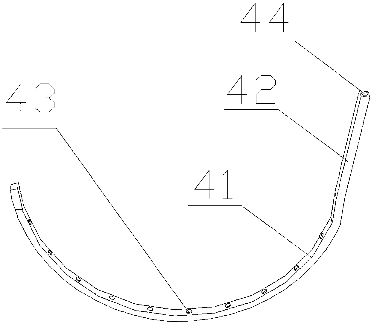
[0030] On the basis of Embodiment 1, a specific dust suction structure is provided, which includes an arc-shaped dust-absorbing strip 4 matching the shape of the spherical glass cover 3, driving the arc-shaped dust-absorbing strip 4 on the spherical glass The driving motor 6 and the vacuum cleaner 7 that move outside the outer surface of the cover 3, wherein the arc-shaped dust-absorbing strip 4 is as figure 2 As shown, the driving motor 6 and the vacuum cleaner 7 are all prior art, and will not be described in detail here; the inside of the arc-shaped dust-absorbing bar 4 is hollow to form a dust-absorbing cavity 44, and the dust-absorbing cavity 44 is communicated with the vacuum cleaner 7. The side of the arc-shaped dust-absorbing bar 4 close to the spherical glass cover 3 is provided with a dust-absorbing pipe 43 communicating with the dust-absorbing cavity 44 , and the opening of the dust-absorbing pipe 43 faces the outer surface of the spherical glass cover 3 .
[0031]...
Embodiment 3
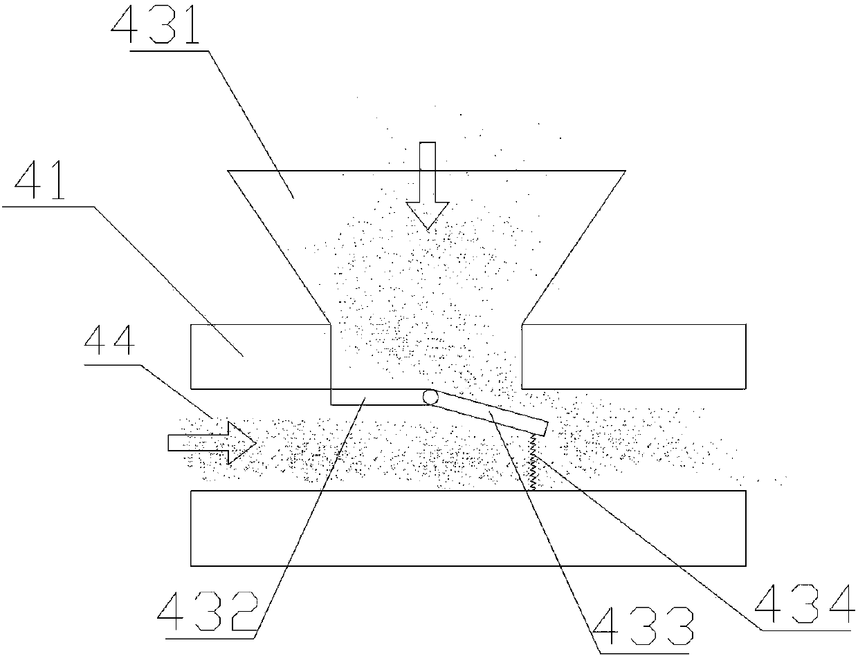
[0034] On the basis of embodiment 2, in order to prevent dust from falling back on the spherical glass cover 3, a specific structural example of a dust suction pipe 43 is provided, and the working state of the dust suction pipe 43 is as follows: image 3 As shown, the dust suction pipe 43 includes a trumpet-shaped suction nozzle 431, the large end of the suction nozzle 431 faces the outer surface of the spherical glass cover 3, and the small mouth end of the suction nozzle 431 communicates with the inside of the arc-shaped dust suction strip 4. The dust suction cavity 44, the connection between the small mouth end of the dust suction nozzle 431 and the dust suction cavity 44 is provided with a fixed sealing plate 432 fixed in the dust suction cavity 44, and the area of the fixed sealing plate 432 is less than The small mouth end of the dust suction nozzle 431, the fixed sealing plate 432 is also rotatably connected with a movable sealing plate 433 that seals the small mouth e...
PUM
 Abstract
Description
Claims
Application Information
 - R&D
- Intellectual Property
- Life Sciences
- Materials
- Tech Scout
- Unparalleled Data Quality
- Higher Quality Content
- 60% Fewer Hallucinations
Browse by: Latest US Patents, China's latest patents, Technical Efficacy Thesaurus, Application Domain, Technology Topic, Popular Technical Reports.
© 2025 PatSnap. All rights reserved.Legal|Privacy policy|Modern Slavery Act Transparency Statement|Sitemap|About US| Contact US: help@patsnap.com


