A drilling and chamfering device suitable for processing steel pipes of different sizes

A chamfering device and technology for steel pipes, applied in the direction of manufacturing tools and other manufacturing equipment/tools, etc., can solve the problems of increasing equipment and labor production costs, affecting the production efficiency of steel pipes, etc., to reduce equipment investment costs, facilitate adjustment and use, and improve The effect of processing efficiency

Active Publication Date: 2019-06-18
常熟市盈博钢管有限公司
View PDF10 Cites 0 Cited by
  • Summary
  • Abstract
  • Description
  • Claims
  • Application Information

AI Technical Summary

Problems solved by technology

[0002] At present, steel pipes are widely used in many fields of industry, such as movable frames of engineering buildings, water transportation in water conservancy and hydropower, and outer pipe protection in the power cable industry. Steel pipes are used in different fields. , requires targeted processing. Generally, steel pipes are required to be polished, drilled, chamfered, etc., but the existing steel pipes are processed separately according to different processing requirements, and are produced separately by different equipment and processes. Although it is more convenient to process in this way, this processing method seriously affects the production efficiency of steel pipes, and increases the production costs of equipment and labor. Improve to make it more in line with the needs of steel pipe production and processing, and promote the development of the enterprise

Method used


Image

  • A drilling and chamfering device suitable for processing steel pipes of different sizes
  • A drilling and chamfering device suitable for processing steel pipes of different sizes
  • A drilling and chamfering device suitable for processing steel pipes of different sizes

Examples


Embodiment 1

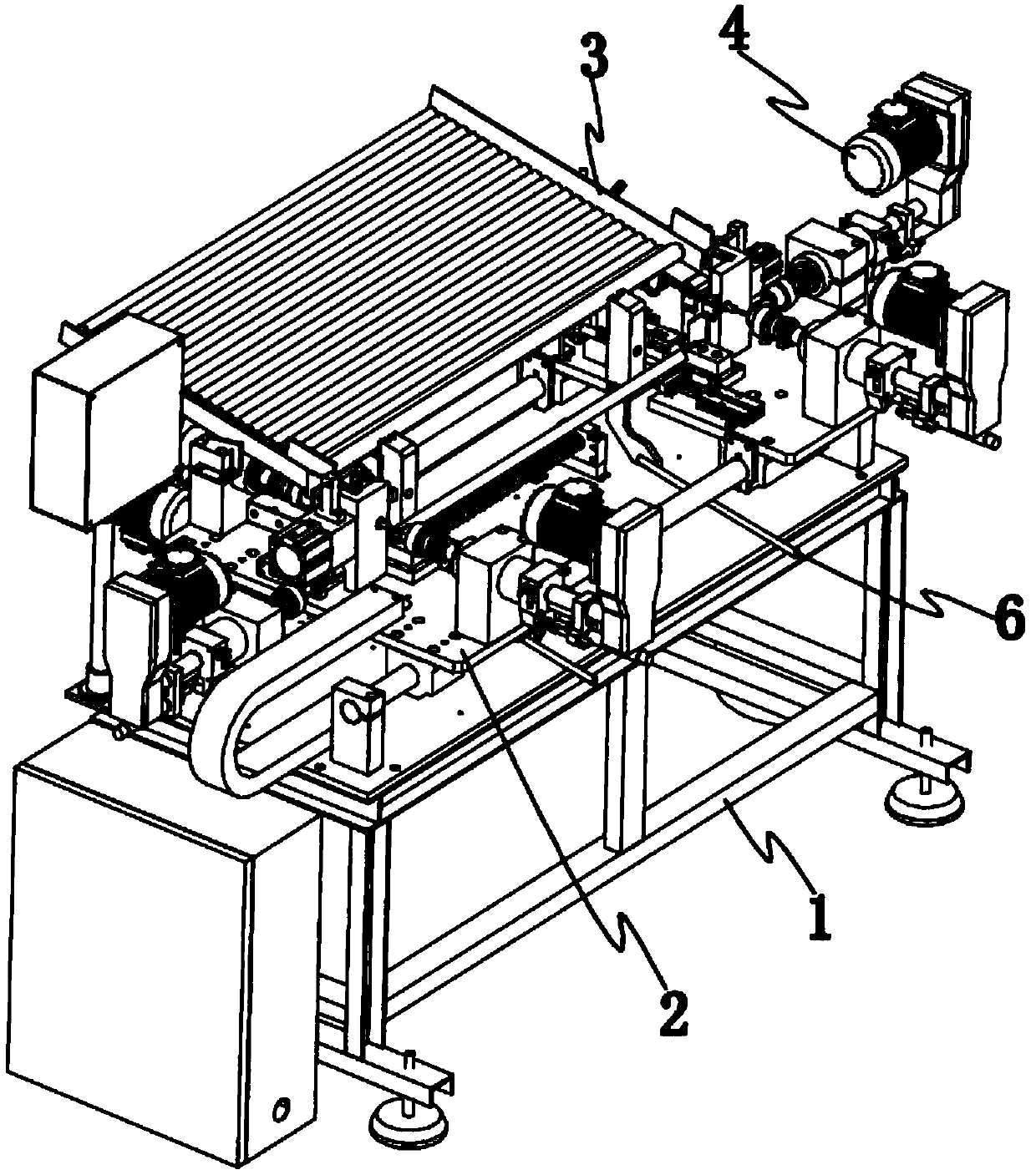
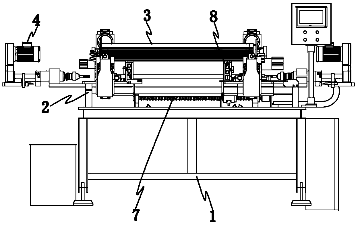
[0037] This device first puts steel pipes one by one from the high outer end of the steel pipe importing frame edge 302 of the steel pipe drilling clamping mechanism 3, and the steel pipe erected on the steel pipe importing frame edge 302 is under the action of gravity, along the steel pipe importing frame edge 302 Rolling down, finally blocked by the upper end limit of the steel pipe limit column 805 of the steel pipe jacking input mechanism 8, when the steel pipe is input and processed, the jacking cylinder 802 of the steel pipe jacking input mechanism 8 is started, and the piston of the jacking cylinder 802 The driving plate 803 on the rod drives the jacking block 807 to move upward along the clamping groove 806 of the steel pipe limiting column 805, so that the steel pipe is ejected from the steel pipe limiting column 805 side to the steel pipe importing frame edge 302, and rolled into the The drilling of the steel pipe drilling and clamping mechanism 3 fixes the notch at t...

Embodiment 2

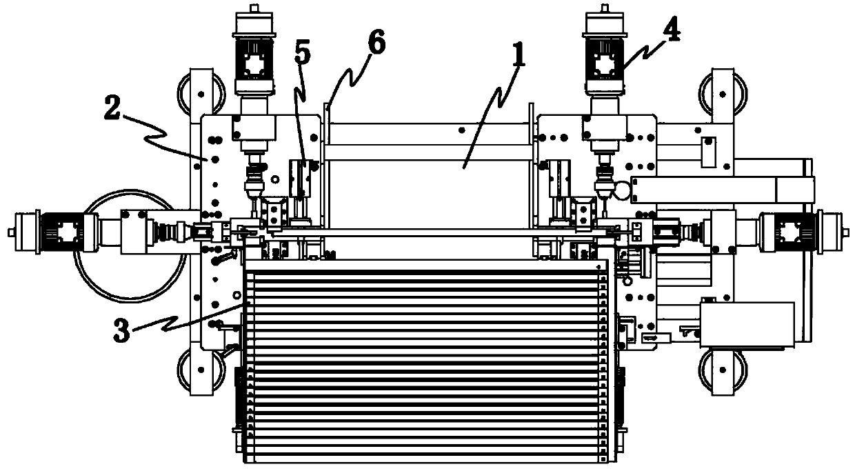
[0039] When the device drills the steel pipe, the steel pipe rolled into the upper notch of the drilling clamping groove block 301 of the steel pipe drilling clamping mechanism 3 is lifted by the adjustment block 304 on the side end groove of the drilling clamping groove block 301 , then start the drilling clamping drive cylinder 303, the drilling clamping drive cylinder 303 piston rod passes through the drilling clamping groove block 301 and connects with the two ends of the steel pipe, so as to realize the fixing of the steel pipe, then start the steel pipe drilling The processing tool driving mechanism 4 on the front and rear sides of the hole clamping mechanism 3, the driving motor 402 of the processing tool driving mechanism 4 drives the rotating drive shaft 403 to rotate through the belt transmission mechanism, and the rotating driving shaft 403 drives the processing tool 407 at the front end to rotate together. When the side pipe surface of the steel pipe is drilled, the...

Embodiment 3

[0041] The device firstly drills the steel pipe, and then chamfers the end of the pipe. After the steel pipe is drilled in the drilling clamping groove block 301 of the steel pipe drilling and clamping mechanism 3, the steel pipe clamps the groove The processing groove of the block 301 falls onto the slot 204 on the opposite end faces of the left workbench 203 and the right workbench 201, wherein the steel pipe is supported by the steel pipe of the steel pipe chamfering clamping mechanism 5 on the cylinder 504 piston rod The rod 505 lifts the steel pipe on the slot 204, and then starts the chamfering and clamping drive cylinder 501 of the steel pipe chamfering and clamping mechanism 5, clamps the steel pipe by the fixed clamp block 503 and the movable clamp block 502, and then starts the steel tube The processing tool driving mechanism 4 on the outer surface of the drilling clamping mechanism 3 performs chamfering processing on the two ends of the steel pipe. In situ, the stee...


PUM


Abstract

The invention relates to a drilling and chamfering device suitable for machining of steel pipes of different sizes. The drilling and chamfering device comprises an equipment table and a worktable mechanism arranged on the equipment table. A steel pipe drilling clamping mechanism and a steel pipe chamfering clamping mechanism are arranged at the upper end of the worktable mechanism. A steel pipe jacking input mechanism is arranged at the position, on the rear side of the steel pipe drilling clamping mechanism, of the upper end surface of the worktable mechanism. Machining tool driving mechanisms are arranged at the positions, on the front side and the rear side of the steel pipe drilling clamping mechanism and at the outer side edge of the steel pipe chamfering clamping mechanism, of the upper end surface of the worktable mechanism. A position adjusting driving mechanism of the worktable mechanism is arranged on the equipment table. The drilling and chamfering device suitable for machining of the steel pipes of the different sizes has the functions of drilling of pipe bodies of the steel pipes and chamfering of the ends of the pipe bodies simultaneously, a previous mode that drilling and chamfering of the steel pipes are conducted separately through different independent equipment is replaced, not only is the machining efficiency improved, but also the input cost of enterprise machining equipment is reduced, and the drilling and chamfering device can be suitable for drilling and chamfering of the steel pipes of the different specifications and sizes, and is wide in application range and convenient to adjust and use.

Description

technical field [0001] The invention relates to the technical field of equipment for processing steel pipe ends, in particular to a drilling chamfering device suitable for processing steel pipes of different sizes. Background technique [0002] At present, steel pipes are widely used in many fields of industry, such as movable frames of engineering buildings, water transportation in water conservancy and hydropower, and outer pipe protection in the power cable industry. Steel pipes are used in different fields. , requires targeted processing. Generally, steel pipes are required to be polished, drilled, chamfered, etc., but the existing steel pipes are processed separately according to different processing requirements, and are produced separately by different equipment and processes. Although it is more convenient to process in this way, this processing method seriously affects the production efficiency of steel pipes, and increases the production costs of equipment and labo...

Claims


Application Information

Patent Timeline
Patent Type & Authority Patents(China)
IPC IPC(8): B23P23/02
CPCB23P23/02
Inventor 王毅军
Owner 常熟市盈博钢管有限公司
Why Eureka
Try Eureka