Supercharge Your Innovation With Domain-Expert AI Agents!

Flexible efficient grinding and polishing device

A high-efficiency, grinding-polishing technology, applied in the direction of grinding/polishing equipment, metal processing equipment, grinding/polishing safety devices, etc., can solve the problems of multi-energy, load energy consumption, large load, etc., and achieve stable and soft swing Effect of stopping and starting, prolonging equipment life

Pending Publication Date: 2018-04-17
广东工科机电有限公司
View PDF8 Cites 2 Cited by
  • Summary
  • Abstract
  • Description
  • Claims
  • Application Information

AI Technical Summary

Problems solved by technology

Such a swing mode is likely to cause the vibration of the swing beam when it stops and the huge load to consume energy when it starts; when the swing beam stops and starts, it needs to overcome a large load, which has a great impact on the stability and service life of the equipment. Consumes more energy at the same time

Method used


Image

  • Flexible efficient grinding and polishing device
  • Flexible efficient grinding and polishing device

Examples


Embodiment 1

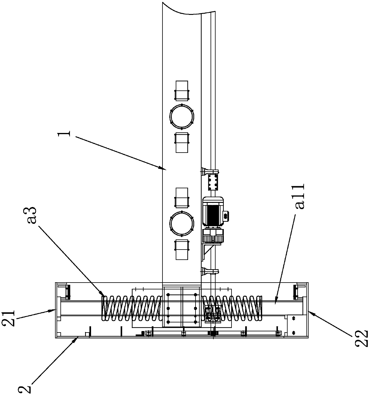
[0013] Embodiment 1, a kind of flexible high-efficiency grinding and polishing equipment, such as figure 1 As shown, the flexible and efficient grinding and polishing equipment includes a frame on which a swing beam 1, a support 2, a power device and an accumulator are arranged, and the support 2 is provided with a reciprocating mechanism perpendicular to the swing beam 1. track, the support 2 also includes a front baffle 21 and a rear baffle 22, the front baffle 21 and the rear baffle 22 are respectively located at the front and rear of the reciprocating track, and the swing beam 1 is provided with a movable connection with the reciprocating track. As for the moving part, the power device drives the swing beam to swing forward and backward along a reciprocating track, and the accumulators are installed in pairs on the front fender 21 and the rear fender 22 respectively, and are connected with the swing beam 1 at the same time. The accumulator is a spring-type accumulator, com...

Embodiment 2

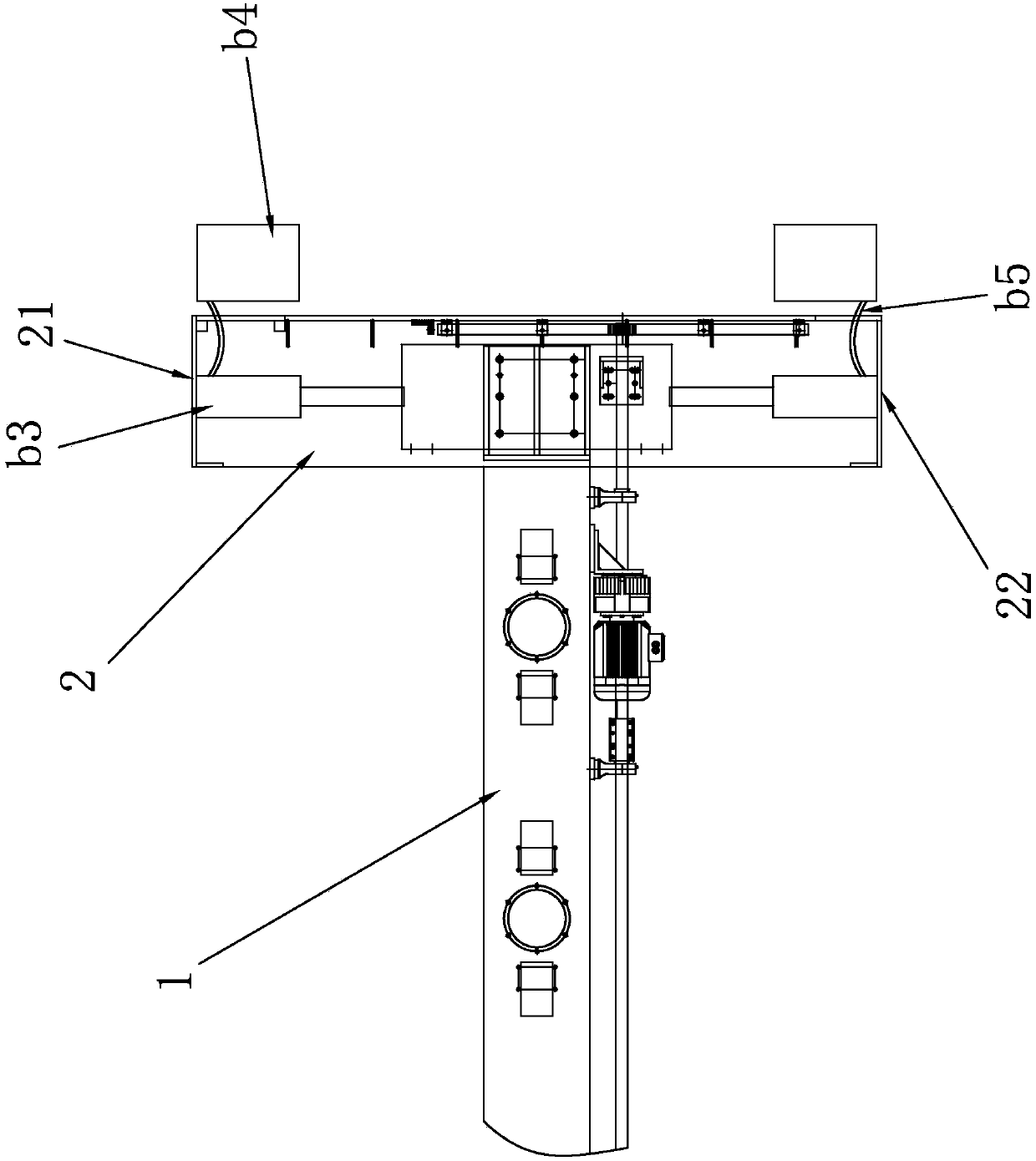
[0014] Example 2, such as figure 2 As shown, the difference between it and Embodiment 1 is that the structure of the accumulator is different, and the accumulator is a gas accumulator, including a hydraulic cylinder b3 and an air bag b4, and the hydraulic cylinder b3 is fixedly installed on the front baffle 21 On the tailgate 22, its piston rod is fixedly connected with the swing beam 1, and the air bag b4 communicates with the hydraulic cylinder b3 through the oil pipe b5. An electromagnetic valve for auxiliary braking is also provided on the oil pipe b5. During the deceleration and braking process of the swing beam 1, the oil in the compression cylinder b3 will be compressed like the air bag b4, and the pressure of the oil in the air bag b4 will increase, consuming the kinetic energy of the swing beam 1; when the swing beam 1 is ready for reverse pneumatic, The pressure in the air bag b4 pushes the swing beam 1 through the compression cylinder b3, and converts the pressure...


PUM


Abstract

The invention discloses a flexible efficient grinding and polishing device. The device comprises a rack, wherein a swinging beam, a supporting seat, a power device and energy storing devices are arranged on the rack; a reciprocating rail which is perpendicular to the swinging beam is arranged on the supporting seat; the supporting seat further comprises a front baffle plate and a rear baffle platewhich are correspondingly positioned at the front and back of the reciprocating rail; the swinging beam is provided with a moving part which is movably connected to the reciprocating rail; the swinging beam is driven through the power device to forwards and backwards swing along the reciprocating rail; the energy storing devices are mounted in pairs on the front baffle plate and the rear baffle plate and are connected to the swinging beam. According to the device, the energy storing devices are capable of effectively buffering and absorbing the kinetic energy of the swinging beam in the pauseof forward-backward swinging and capable of effectively feeding back the energy to reverse start of the swinging beam. Therefore, the swinging beam can be gently stopped and started, and smooth and steady swinging is realized and beneficial for the stable running of the grinding and polishing device, and as a result, the service life of the device is prolonged.

Description

technical field [0001] The invention relates to the technical field of plate processing equipment such as ceramics and stone materials. Background technique [0002] The profiling grinding and polishing equipment can realize the periodic swing of the grinding and polishing head in the process of processing plates and tiles, so as to achieve uniform grinding or polishing effect. It mainly relies on the swing beam mechanism to realize the periodic swing of the grinding and polishing head. It specifically includes a swing beam, a support and a power device. The support is provided with a reciprocating track perpendicular to the swing beam. The swing beam is provided with moving parts that are movably connected to the reciprocating track. The power device drives the swing beam forward and backward along the reciprocating track. swing. [0003] The swinging beam completely depends on the mechanical brake of the reducer, and the reducer is a self-locking brake or a servo motor o...

Claims


Application Information

Patent Timeline
Patent Type & Authority Applications(China)
IPC IPC(8): B24B7/22B24B55/00B24B41/00
CPCB24B7/22B24B41/007B24B55/00
Inventor 龙其瑞黄军龙伍洋黄晓军
Owner 广东工科机电有限公司
Features
  • R&D
  • Intellectual Property
  • Life Sciences
  • Materials
  • Tech Scout
  • Unparalleled Data Quality
  • Higher Quality Content
  • 60% Fewer Hallucinations
Learn More