
Fan motor

A fan motor and motor technology, applied in the direction of electromechanical devices, electrical components, liquid fuel engines, etc., can solve the problems of fan motor drive and influence of abnormal sound, and achieve the effect of suppressing the influence

Inactive Publication Date: 2018-04-17
NIDEC CORP
View PDF8 Cites 1 Cited by
  • Summary
  • Abstract
  • Description
  • Claims
  • Application Information

AI Technical Summary

Problems solved by technology

Therefore, when the case is dropped or pressed, the inner wall of the case comes into contact with the fan motor, which may cause abnormal noise or affect the drive of the fan motor.

Method used


Image

  • Fan motor
  • Fan motor
  • Fan motor

Examples


no. 1 approach >

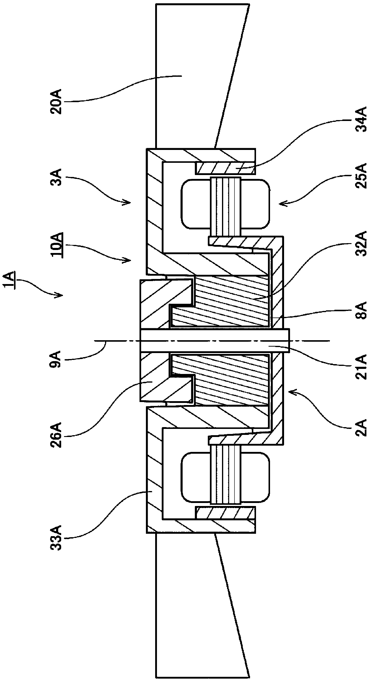
[0020] figure 1 It is a longitudinal cross-sectional view of 1A of fan motors concerning 1st Embodiment of this invention. like figure 1 As shown, the fan motor 1A has a motor 10A and an impeller 20A. The motor 10A includes: a stationary part 2A having a stator 25A; and a rotating part 3A. The rotating part 3A has a magnet 34A facing the stator 25A in the radial direction, and is rotatably supported by the stationary part 2A with the center axis 9A extending up and down as the center of the bearing part 8A. The impeller 20A rotates together with the rotating part 3A of the motor 10A.

[0021] The stationary portion 2A has a shaft 21A and an upper thrust portion 26A. The shaft 21A is a cylindrical member arranged along the central axis 9A. The upper thrust portion 26A extends radially outward from the upper portion of the shaft 21A.

[0022] The rotating portion 3A has a sleeve portion 32A and a rotor hub portion 33A. The inner peripheral surface of the sleeve portion 32...

no. 2 approach >

[0025]

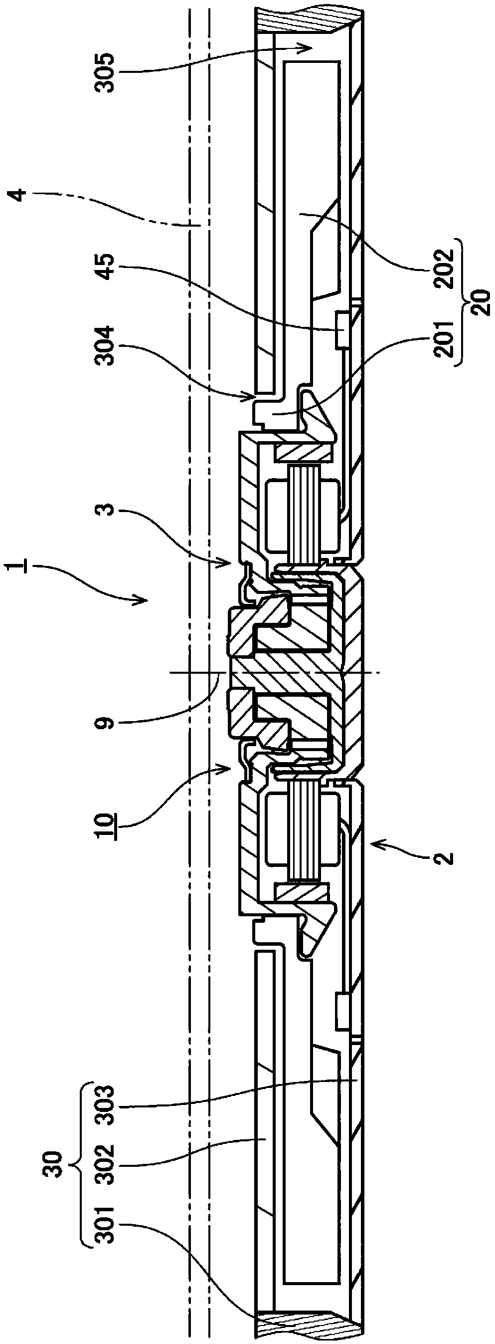
[0026] Next, a second embodiment of the present invention will be described. figure 2 It is a longitudinal cross-sectional view of the fan motor 1 which concerns on 2nd Embodiment.

[0027] The fan motor 1 is installed inside a casing 4 of a notebook computer or the like, and serves as a device for supplying an air flow for cooling. like figure 2 As shown, the fan motor 1 of this embodiment includes the motor 10 , the impeller 20 , and the casing 30 .

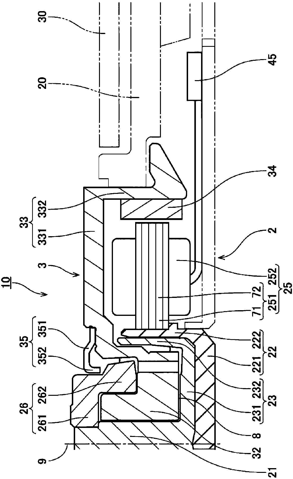
[0028] The motor 10 is a device that rotates an impeller 20 to be described later in accordance with a drive current. First, the configuration of the motor 10 will be described. image 3 as well as Figure 4 It is a partial longitudinal cross-sectional view of the motor 10 . like image 3 As shown, the motor 10 includes a stationary portion 2 that is relatively stationary with respect to a housing 30 to be described later, and a rotating portion 3 that is rotatably supported by the stationary portion 2 and ro...


PUM


Abstract

The invention provides a fan motor that includes a motor and an impeller arranged to rotate together with a rotating portion of the motor. The motor includes a stationary portion including a stator, and the rotating portion, which includes a magnet arranged opposite to the stator and which is supported through a bearing portion to be rotatable about a central axis extending in a vertical directionwith respect to the stationary portion. The stationary portion includes a shaft arranged to extend along the central axis, and an upper thrust portion arranged to extend radially outward from an upper portion of the shaft. The rotating portion includes a sleeve portion arranged radially opposite to the shaft and axially opposite to the upper thrust portion; and a rotor hub portion arranged to extend in an annular shape around the sleeve portion, and arranged to have the impeller fixed thereto. An upper end of the stationary portion is arranged at a level higher than that of an upper end of the rotating portion.

Description

technical field [0001] The present invention relates to a fan motor. Background technique [0002] Conventionally, a high-performance electronic device such as a notebook computer or a tablet computer is equipped with a fan motor for cooling the CPU and the like inside the casing. When the fan motor is driven, an airflow is generated inside the casing. Thereby, heat accumulation in the inside of the casing is suppressed. The structure of the conventional fan motor is described in, for example, Japanese Laid-Open Patent Publication No. 2013-032769. [0003] In recent years, with thinning of notebook computers, tablet computers, and the like, the distance between the inner wall of the casing and the fan motor installed inside the casing has been shortened. Therefore, when the casing is dropped or the casing is pressed, the inner wall of the casing comes into contact with the fan motor, which may generate abnormal noise or affect the driving of the fan motor. SUMMARY OF TH...

Claims


Application Information

Patent Timeline
Patent Type & Authority Applications(China)
IPC IPC(8): F04D29/00F04D29/66F04D25/08H02K7/14
CPCF04D25/08F04D29/002F04D29/663H02K7/14F04D25/0613F04D29/0513F04D29/057H02K5/1677F04D29/063F04D19/002F04D25/0606F04D29/051F04D29/281F04D29/4226H02K5/16
Inventor 玉冈健人
Owner NIDEC CORP
Learn More