Pressure valve

A pressure relief valve and spool technology, applied in the field of pressure relief valves, can solve problems such as high cost and achieve low manufacturing costs

Inactive Publication Date: 2019-10-18
DANFOSS POWER SOLUTIONS GMBH & CO
View PDF5 Cites 0 Cited by
  • Summary
  • Abstract
  • Description
  • Claims
  • Application Information

AI Technical Summary

Problems solved by technology

Of course, in the manufacturing process, this leads to considerable costs not only for the valve itself, but also for the hydraulic or pneumatic unit using such a valve

Method used


Image

  • Pressure valve
  • Pressure valve
  • Pressure valve

Examples


Embodiment Construction

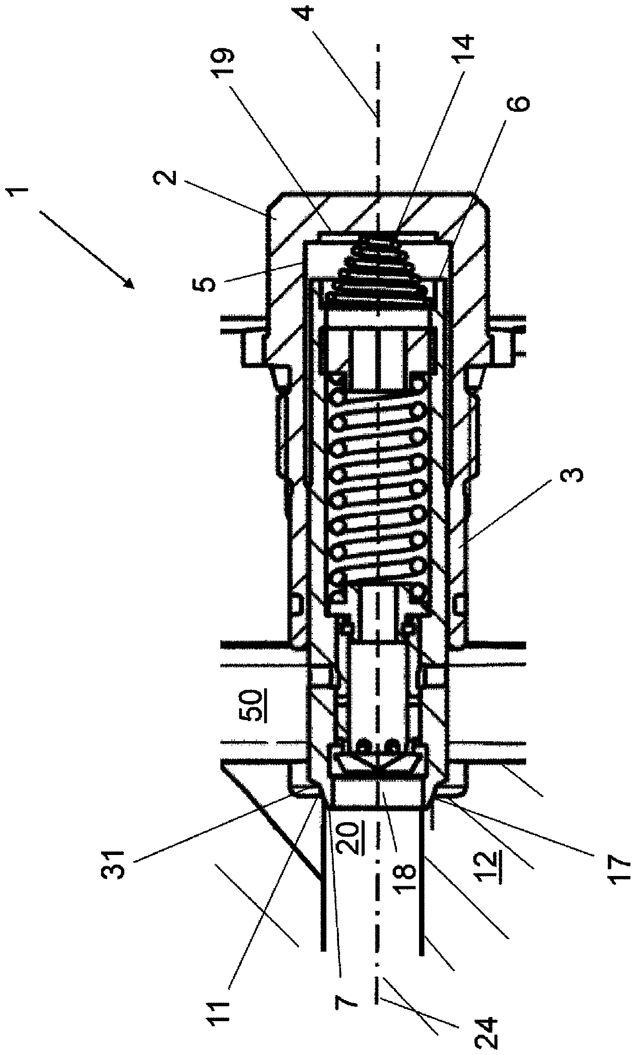
[0021] figure 1 A longitudinal section through a pressure relief valve 1 according to the prior art is shown. The valve housing 2 is of generally cylindrical shape with a longitudinal axis 4 . The spool 3 is slidable between two positions in the cylindrical bore 5 of the housing 2 . exist figure 1In the first position shown, the front end or mouth 18 of the pressure relief spool 3 is, for example, in direct sealing contact with the valve seat 11 of the pressure line 20 in the mounting cavity 12 of the hydraulic system. The sealing contact is provided under the action of the pressure relief valve spring 14 which acts on the actuating side 6 of the pressure relief valve plug 3 and abuts against the bottom surface 19 of the bore 5 thereby pushing towards the valve seat 11 Pressure relief spool 3. In this first closed position of the pressure relief spool 3 , fluid flow between the pressure line 20 and the fluid channel 50 is prevented as long as the pressure in the pressure l...


PUM


Abstract

A pressure relief valve comprising a valve housing in which is accommodated a cylindrical pressure relief spool operable on both sides, the pressure relief spool being able to move longitudinally along the cylindrical bore in the valve housing Axis slide. The pressure relief spool is movable to a first position by a first force acting on an actuating side of the pressure relief spool, and is movable to a second position by pressure acting on a sealing side of the pressure relief spool. Positioned on the sealing side of the pressure relief spool is a double seal, rotationally symmetric poppet having an axis of rotation, a first convex sealing surface and a second convex sealing surface. A first sealing surface facing away from the pressure relief spool is configured to seal against the outer valve seat. Said second sealing surface facing the stepped hole in the spool is provided for sealing the smaller diameter of the stepped hole. The poppet valve and the axis of rotation of the poppet valve can be inclined relative to the longitudinal axis of the cylindrical bore in the pressure valve housing.

Description

technical field [0001] The invention relates to a pressure relief valve according to the preamble of claim 1, comprising a valve housing in which a double-sided cylindrical spool is accommodated in the valve housing along the longitudinal The longitudinal axis of the hole slides and can be pressed / pushed on both sides. Background technique [0002] Such pressure valves are known in the art. An example of this is in figure 1 shown in . This type of pressure relief valve is used in hydraulic or pneumatic systems, for example to limit the pressure in specific branches or lines of individual circuits. In order to do this, the pressure relief valve has a housing in which the spool or the piston can be moved between two limit positions under the pressure acting on the spool and / or under the action of a spring. In each of these positions, the spool under pressure opens or closes a particular passage for fluid. To close this passage for fluid, the sealing surface of the spool i...

Claims


Application Information

Patent Timeline
Patent Type & Authority Patents(China)
IPC IPC(8): F16K17/04F16K17/164F16K1/36
CPCF16K1/36F16K17/04F16K17/164F16K17/105F16K31/1221
Inventor 韦斯特菲尔德·马丁托马斯·莱因哈特
Owner DANFOSS POWER SOLUTIONS GMBH & CO
Why Eureka
Try Eureka