Learning teaching aid system of identifying and detecting positional relation
A technology for detecting position and relationship, which is applied in the field of learning teaching aid system, can solve problems such as the inability to automatically identify whether the assembly is correct or not, lack of electronic means, and non-physical operation, etc. It achieves huge educational and market value, low development and production costs, The effect of faster and more accurate feedback
- Summary
- Abstract
- Description
- Claims
- Application Information
AI Technical Summary
Problems solved by technology
Method used
Image
Examples
Embodiment 1
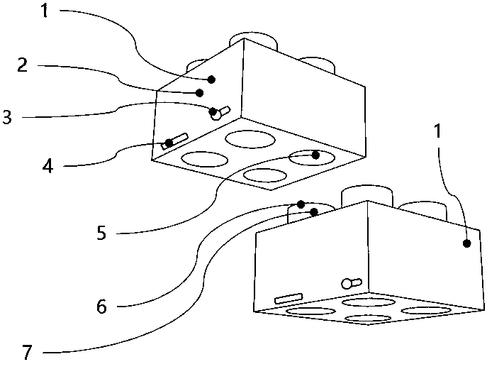
[0025] combine figure 1 , the learning teaching aid system for identifying and detecting positional relationships of the present application includes at least two (multiple) building blocks 1 of different shapes, the building blocks 1 have a built-in single-chip microcomputer 2, a plug 6 is provided on the top of the building block 1, and a socket 5 is provided below, and the plugs 6 is matched with the socket 5, the plug 6 has a built-in coding resistor 7, and the resistance value of the built-in coding resistor 7 is different for different building blocks 1 and different positions, which is used to distinguish different building blocks 1 and splicing positions; The conductive contacts are connected to the single-chip microcomputer 2; the building block 1 is also provided with a power switch, a mode selection switch 3, a red LED lamp bead 4, and a built-in lithium battery; the mode selection switch 3 is provided with a setting mode and an assembly mode. mode, set the target s...
Embodiment 2
[0029] The teaching aid system for identifying and detecting positional relationships of the present invention includes a plurality of building blocks 1 of different shapes, with a built-in single-chip microcomputer 2 control board, a plug 6 is provided above the building block 1, and a socket 5 is provided below, and the plug 6 has a built-in coding resistor 7 and socket 5. There are conductive contacts inside and are connected to the single chip microcomputer 2 control board. The building block 1 is also equipped with a power switch, a mode selection switch 3, a red LED lamp bead 4, and a built-in lithium battery.
[0030] Function description: (1) Building blocks 1 of different shapes that can be assembled; (2) Building block 1 plug 6 has a built-in coding resistor 7. The resistance values of different building blocks 1 and different positions are different, which are used to distinguish different building blocks 1 and splicing positions; (3) There is a conductive contact ...
Embodiment 3
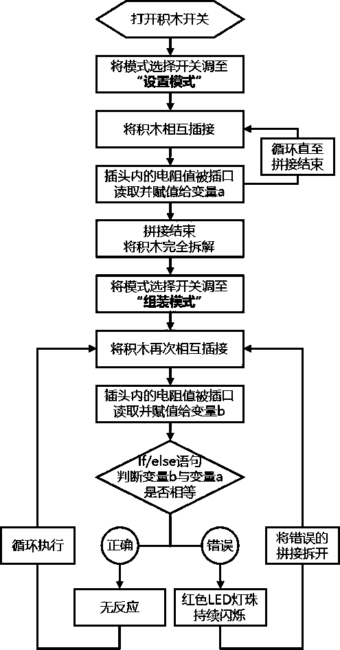
[0032] combine figure 2 , this embodiment is an application embodiment, and the specific operation method is as follows:
[0033] 1) Turn on the switch of building block 1;
[0034] 2) Turn the mode selection switch 3 on the building block 1 to "setting mode";
[0035] 3) Connect building blocks 1 to each other;
[0036] 4) The resistance value of the coding resistor 7 on the plug 6 is read by the single chip microcomputer 2 where the socket 5 is located through the contact of the socket 5;
[0037] 5) The resistance value of the encoding resistor 7 is substituted into the built-in program of the microcontroller 2, and assigned to a variable a;
[0038] 6) After splicing, set the mode selection switch 3 of each building block 1 to "assembly mode";
[0039] 7) Connect the building blocks 1 to each other again;
[0040] 8) The resistance value of the coding resistor 7 on the plug 6 is read by the single-chip microcomputer 2 where the socket 5 is located through the contact...
PUM
 Abstract
Description
Claims
Application Information
 - R&D
- Intellectual Property
- Life Sciences
- Materials
- Tech Scout
- Unparalleled Data Quality
- Higher Quality Content
- 60% Fewer Hallucinations
Browse by: Latest US Patents, China's latest patents, Technical Efficacy Thesaurus, Application Domain, Technology Topic, Popular Technical Reports.
© 2025 PatSnap. All rights reserved.Legal|Privacy policy|Modern Slavery Act Transparency Statement|Sitemap|About US| Contact US: help@patsnap.com


