Ultrasonic vibration assisted drawing forming device and method for thin-walled micro fine pipe

An ultrasonic vibration and microtube technology, applied in metal drawing forming tools, metal wire drawing, metal processing equipment, etc., can solve the problems of low surface quality and easy fracture, achieve good surface quality, improve plastic performance, and solve the problem of stripping. The effect of the puzzle

Inactive Publication Date: 2018-04-20
HARBIN INST OF TECH
View PDF4 Cites 6 Cited by
  • Summary
  • Abstract
  • Description
  • Claims
  • Application Information

AI Technical Summary

Problems solved by technology

[0003] The purpose of the present invention is to solve the problems of low surface quality and easy breakage during drawing and forming of thin-walled microtubes, and propose an ultrasonic vibration-assisted drawing device and method for thin-walled microtubes

Method used


Image

  • Ultrasonic vibration assisted drawing forming device and method for thin-walled micro fine pipe

Examples


specific Embodiment approach 1

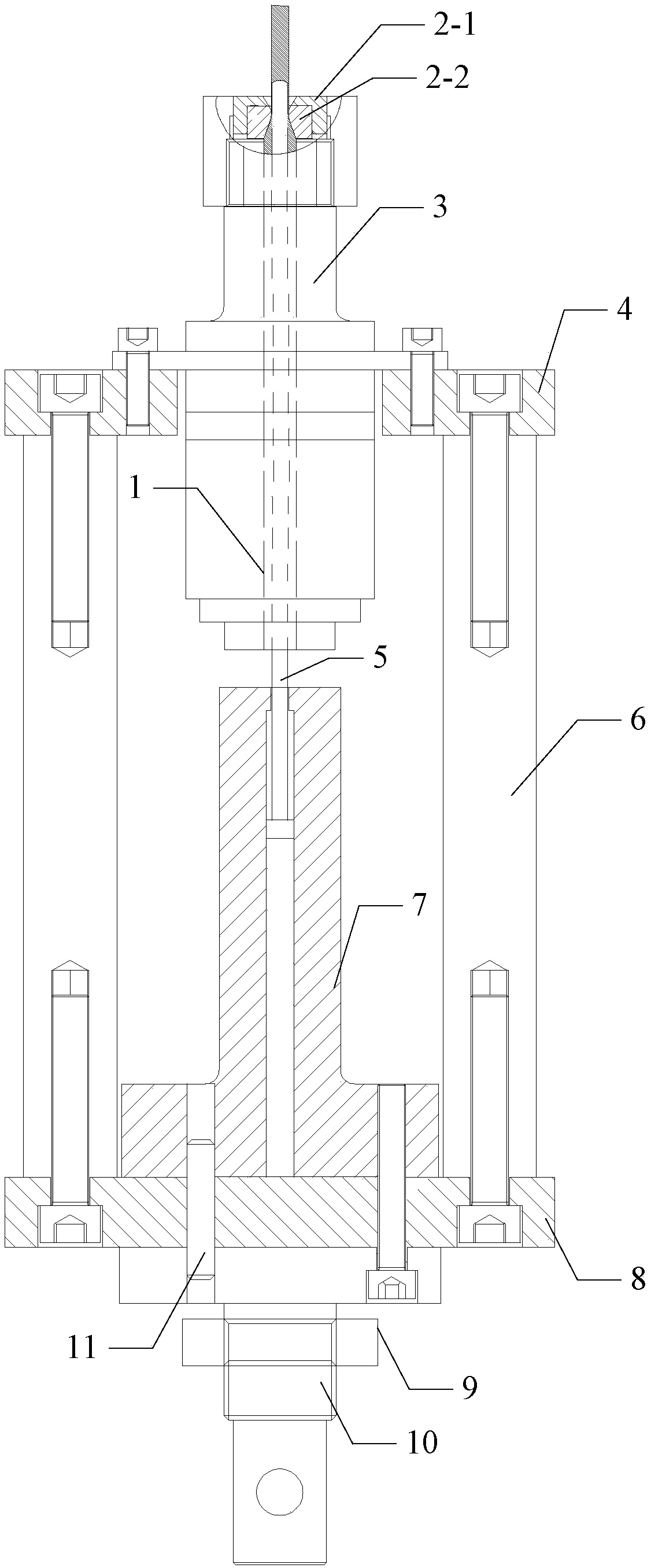
[0020] Specific implementation mode one: combine figure 1 To illustrate this embodiment, the thin-walled microtube ultrasonic vibration-assisted drawing forming device described in this embodiment includes a drawing die, an ultrasonic vibrator 3, an upper die holder 4, a drawing mandrel 5, a support column 6, and a mandrel guide Seat 7, lower mold seat 8, fixing nut 9 and connector 10;

[0021] One end of the connector 10 is fixedly connected with the lower machine base of the tensile testing machine; the other end of the connector 10 is fixed on the bottom surface of the lower mold base 8 by a fixing nut 9;

[0022] The mandrel guide seat 7 is arranged on the top surface of the lower mold base 8;

[0023] The bottom end of the ultrasonic vibrator 3 passes through the upper mold base 4, and the ultrasonic vibrator 3 is fixed on the upper mold base 4;

[0024] The drawing die is tightly and rigidly connected to the top of the ultrasonic vibrator 3; the drawing die is fixed on...

specific Embodiment approach 2

[0029] Specific embodiment 2: This embodiment is to further limit the thin-walled microtube ultrasonic vibration assisted drawing forming device described in specific embodiment 1. In this embodiment, the drawing die includes a die support member 2- 1 and die insert 2-2;

[0030] The die insert 2-2 is tightly and rigidly connected to the top of the ultrasonic vibrator 3;

[0031] The die supporting part 2-1 supports and wraps the outside of the die inserting part 2-2.

[0032] In this embodiment, the die supporting part 2 - 1 and the die inserting part 2 - 2 reduce the difficulty and cost of drawing forming of the drawing die, and facilitate the replacement of the drawing die.

specific Embodiment approach 3

[0033] Embodiment 3: This embodiment further defines the ultrasonic vibration-assisted drawing and forming device for thin-walled microtubes described in Embodiment 1. In this embodiment, a pin 11 is also included;

[0034] Both the lower die base 8 and the mandrel guide seat 7 are provided with pin holes, and the pins 11 pass through the pin holes of the lower die base 8 and the pin holes of the mandrel guide seat 7 at the same time to complete the alignment of the die base 8 and the mandrel. The positioning of the guide seat 7.


PUM


Abstract

The invention discloses an ultrasonic vibration assisted drawing forming device and method for a thin-walled micro fine pipe and relates to a thin-walled micro fine pipe ultrasonic vibration assisteddrawing forming technology in order to solve the problems that during drawing forming of the thin-walled micro fine pipe, the surface quality is low, and breakage is easily caused. According to the ultrasonic vibration assisted drawing forming device and method for the thin-walled micro fine pipe, a connector is fixedly connected with a stretching testing machine; the connector is fixed to a lowermold base; a mandrel guiding base is arranged on the lower mold base; an ultrasonic vibrator is fixed to an upper mold base; a drawing female mold is in close rigidity connection with the ultrasonicvibrator; a supporting column is supported between the upper mold base and the lower mold base; a drawing mandrel is fixed to the mandrel guiding base, and sequentially penetrates the ultrasonic vibrator and the drawing female mold, and the drawing mandrel is higher than the drawing female mold; and drawing forming on a pipe blank is completed under the joint effect of the drawing female mold andthe drawing mandrel. The beneficial effects are that the surface quality of the thin-walled fine pipe formed in a drawing manner is better, and the ultrasonic vibration assisted drawing forming deviceand method for the thin-walled micro fine pipe is applicable to drawing forming of the metal thin-walled micro fine pipe.

Description

technical field [0001] The invention relates to a thin-wall microtube ultrasonic vibration assisted drawing forming technology. Background technique [0002] Thin-walled microtubes are widely used in refrigeration industries such as air conditioners and refrigerators. When the wall thickness is reduced to less than 100 μm, the drawing deformation is extremely difficult, and the forming quality is difficult to guarantee. Especially in recent years, due to the traction of demand, some hard-to-deform materials such as titanium alloys and high-temperature alloys have been applied to thin-walled microtubes, which are more difficult to process and manufacture, and are prone to fracture failures, and the uniformity of wall thickness and surface quality, etc. Difficult to control and in some cases impossible to manufacture. Therefore, the traditional thin-walled microtube manufacturing process cannot meet the new requirements. Contents of the invention [0003] The object of th...

Claims


Application Information

Patent Timeline
Patent Type & Authority Applications(China)
IPC IPC(8): B21C1/24B21C3/00
CPCB21C1/24B21C3/00
Inventor 王春举郭斌单德彬万升祥朱昌琼刘洋徐杰王磊磊汪鑫伟
Owner HARBIN INST OF TECH
Why Eureka
Try Eureka