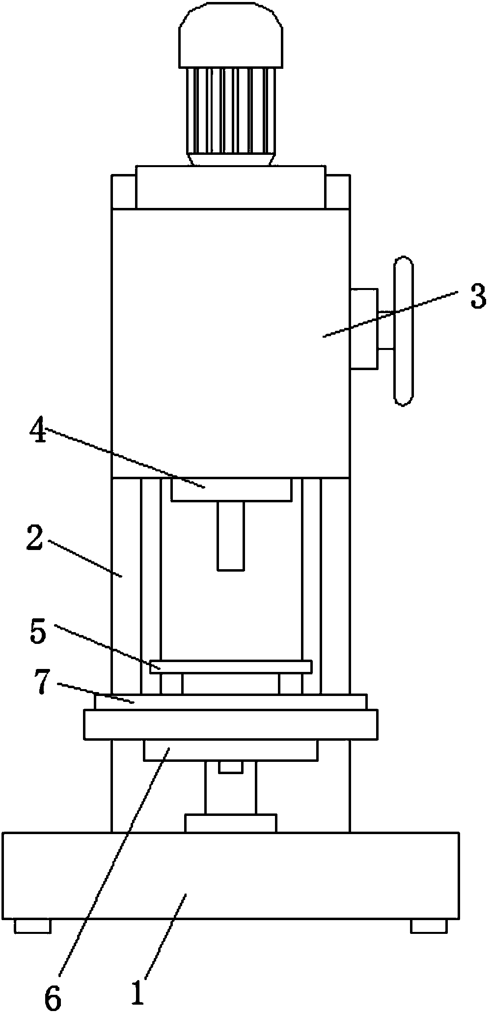
Vertical driller facilitating replacing of fixing device
A technology of vertical drilling machine and fixing device, which is applied to positioning device, components of boring machine/drilling machine, clamping and other directions, can solve problems such as unsatisfactory clamping effect, and achieve the effect of wide range of use, time saving and cost saving.
- Summary
- Abstract
- Description
- Claims
- Application Information
AI Technical Summary
Problems solved by technology
Method used
Image

Examples
Embodiment 1
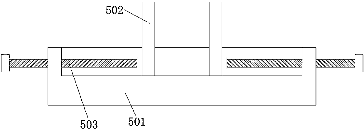
[0032] see image 3 , the positioning mechanism 5 includes a plate body 501, the top of the plate body 501 is slidingly installed with a splint 502, the number of splints 502 is two, and threaded rods I 503 are movably installed on the two splints 502, and the top of the plate body 501 is provided with a concave groove, the bottom end of splint 502 extends to the inside of the groove, and the threaded rod I503 runs through the groove and extends to one side of the plate body 501, the number of threaded rods I503 is two, and the two threaded rods I503 are respectively connected to the plate body 501 are threadedly connected. When the workpiece to be drilled is prismatic, use a fixing mechanism to rotate the threaded rod I503. When the threaded rod I503 rotates, the threaded rod I503 and the plate body 501 are threaded. Therefore, the threaded rod I503 It will move, and when the threaded rod I503 moves, it will push the clamping plate to move, and cooperate with the two clamping...
Embodiment 2
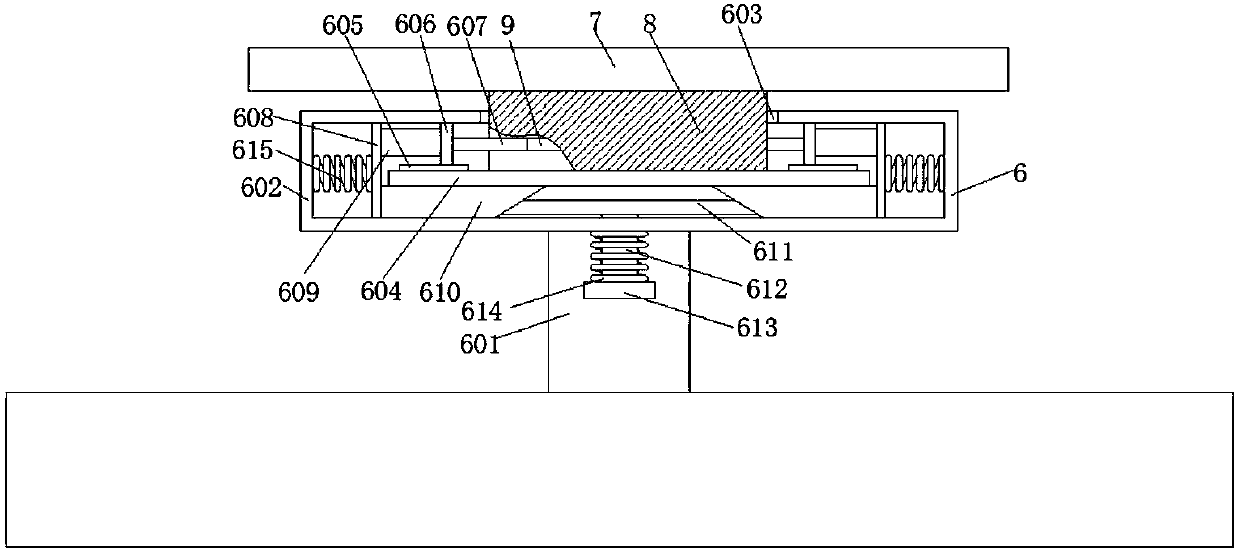
[0034] see Figure 4 and 5, the positioning mechanism 5 includes a placement box 24, the top of the placement box 24 is provided with a groove, and the bottom of the groove of the placement box 24 is slidably equipped with a clamping block 25, and one side of the clamping block 25 is fixedly connected with one end of the screw rod 26 , one end of the screw rod 26 runs through the threaded sleeve 10 and is threadedly connected with the threaded sleeve 10, one end of the threaded sleeve 10 is movably connected with one side of the inner wall of the groove, and the outer surface of the threaded sleeve 10 is sleeved with a worm gear I11, which is placed on the box 24 A worm I12 compatible with the worm gear I11 is installed movably. The bottom end of the worm I12 extends into the inner cavity of the placement box 24 and is fixedly sleeved with the driven wheel 13, and the inside of the placement box 24 is provided with a The driving wheel 14, the shaft center of the driving wheel...
Embodiment 3
[0036] see Figure 6 , the positioning mechanism 5 includes a fixed block 19, the top of the fixed block 19 has a groove, and the inside of the groove is slidably installed with a movable plate 20, and the movable plate 19 is provided with a threaded rod II 21, between the threaded rod II 21 and the movable plate 20 and the bottom of the threaded rod II 21 is flexibly connected with the bottom of the inner wall of the groove. A cover plate 22 is threaded on the threaded rod II 21. The cover plate 22 is located above the fixed block 19, and the cover plate 22 is provided with an opening The hole 23 and the opening 23 on the cover plate 22 are in the shape of a truncated cone. When the workpiece to be processed is a spherical object, the fixing mechanism 5 mentioned in the third embodiment is adopted. When in use, the cover plate 22 is located at the highest point, spherical Put the workpiece into the groove, then turn the threaded rod II21, so that the movable plate 20 rises, a...
PUM
 Abstract
Description
Claims
Application Information
 - R&D
- Intellectual Property
- Life Sciences
- Materials
- Tech Scout
- Unparalleled Data Quality
- Higher Quality Content
- 60% Fewer Hallucinations
Browse by: Latest US Patents, China's latest patents, Technical Efficacy Thesaurus, Application Domain, Technology Topic, Popular Technical Reports.
© 2025 PatSnap. All rights reserved.Legal|Privacy policy|Modern Slavery Act Transparency Statement|Sitemap|About US| Contact US: help@patsnap.com