Eureka AIR delivers breakthrough ideas for toughest innovation challenges, trusted by R&D personnel around the world.

Lathe fixture

A lathe fixture and clamping part technology, which is applied in the field of lathe fixtures, can solve the problems of unstable placement position, time-consuming and labor-intensive, and unsatisfactory parts processing effect.

Inactive Publication Date: 2018-04-20
江门市坐标光电科技有限公司
View PDF0 Cites 2 Cited by
  • Summary
  • Abstract
  • Description
  • Claims
  • Application Information

AI Technical Summary

Problems solved by technology

[0002] In the field of lamp parts production, it is often necessary to cut or polish the plate-shaped or tube-mounted lamp body installation parts. In the prior art, clips or both hands are usually used to hold the parts, which is often time-consuming and laborious, and the placement position is unstable. Unsatisfactory machining effect on parts

Method used


Image

  • Lathe fixture

Examples


Embodiment Construction

[0010] The idea, specific structure and technical effects of the present invention will be clearly and completely described below in conjunction with the embodiments and accompanying drawings, so as to fully understand the purpose, features and effects of the present invention. Apparently, the described embodiments are only some, not all, embodiments of the present invention, and other embodiments obtained by those skilled in the art without creative efforts all fall within the protection scope of the present invention.

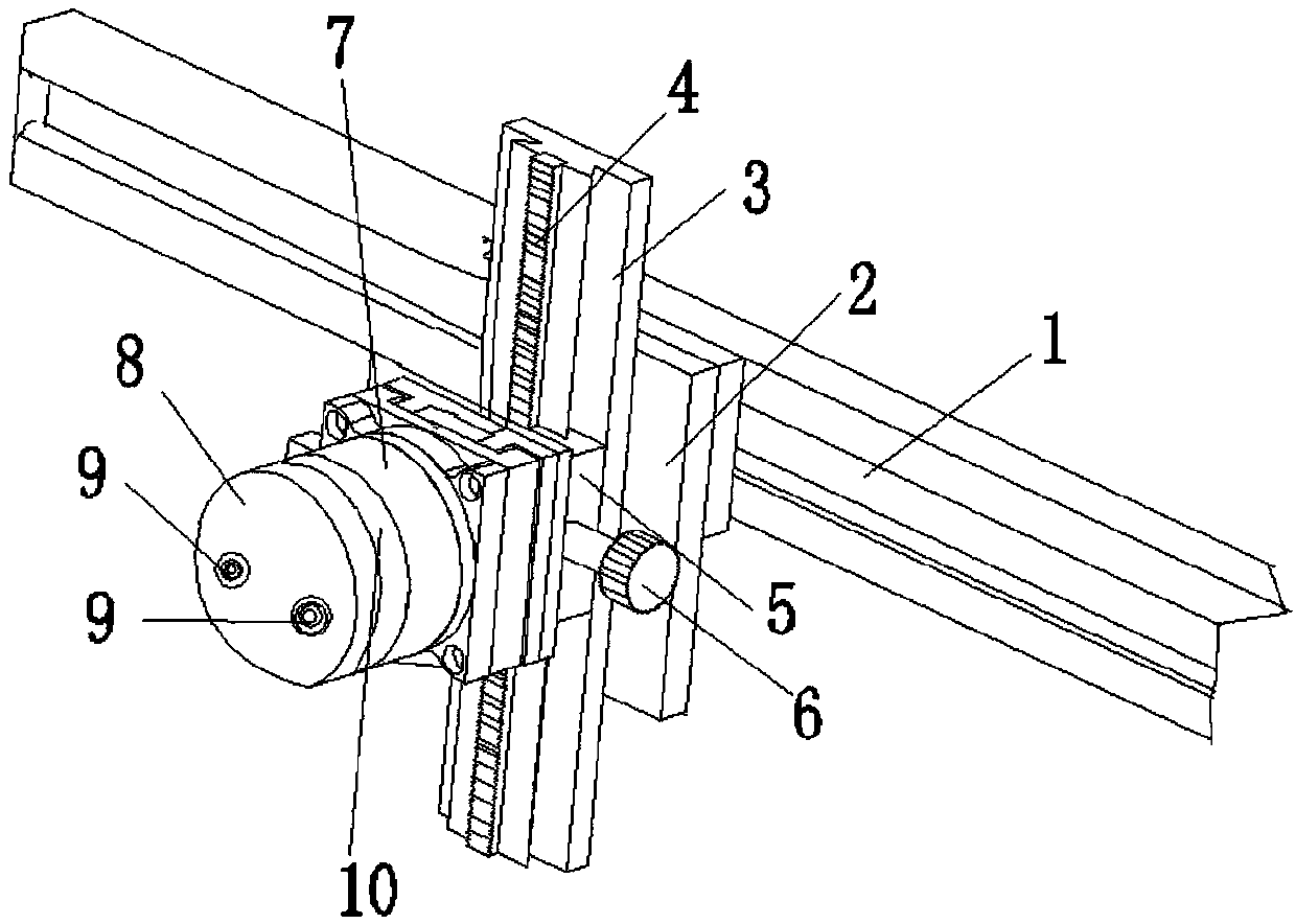
[0011] Such as figure 1 As shown, a lathe fixture includes a horizontal slide rail 1, a slider 2 that is arranged on the horizontal slide rail 1 and can slide along the horizontal slide rail 1, and a fixing plate 3 is provided on the back of the slider 2, A vertical rack 4 is arranged on the fixed plate 3, and a moving block 5 is arranged on the rack 4, and a gear is arranged in the moving block 5, and the gear is engaged with the rack 4. , the outside of th...


PUM


Abstract

The invention discloses a lathe fixture, which comprises a horizontal slide rail, a slider arranged on the horizontal slide rail, a fixed plate is arranged on the back of the slider, a rack is arranged on the fixed plate, and a moving block is cooperatingly arranged on the rack. A gear is arranged in the block, and the gear meshes with the rack. The front part of the moving block is provided with a first clamping part. At least one screw hole is provided in the first clamping part. The front part of the first clamping part is provided with a second Two clamping parts, the first clamping part and the second clamping part are non-contact connected together by screws. The present invention can change the horizontal position of the processing part through the movement of the slide block on the horizontal track, adjust the height of the processing part by adjusting the position of the rack and the gear, and adjust the screw on the second clamping part and the first clamping part The connection of the screw holes on the holding parts can adjust the spacing of the clamping space between the two clamping parts, so as to clamp processed parts with different thicknesses.

Description

technical field [0001] The invention relates to the technical field of clamps, in particular to a lathe clamp. Background technique [0002] In the field of lamp parts production, it is often necessary to cut or polish the plate-shaped or tube-mounted lamp body installation parts. In the prior art, clips or both hands are usually used to hold the parts, which is often time-consuming and laborious, and the placement position is unstable. The processing effect on the part is not ideal. Contents of the invention [0003] Based on the deficiencies of the prior art, the object of the present invention is to provide a lathe fixture that can move the position of the processing parts arbitrarily and improve the clamping effect. [0004] To achieve the above object, the technical solution of the present invention is: [0005] A lathe clamp, characterized in that it includes a horizontal slide rail, a slider arranged on the horizontal slide rail and capable of sliding along the ho...

Claims


Application Information

Patent Timeline
Patent Type & Authority Applications(China)
IPC IPC(8): B23Q3/06B23Q1/25
CPCB23Q3/06B23Q1/25
Inventor 钟锦海
Owner 江门市坐标光电科技有限公司
Why Eureka
Eureka Blog
Learn More