Sheet cutting machine

A technology of sheet cutting machine and frame, applied in the directions of lamination auxiliary operation, metal processing, winding strip, etc., can solve the problems of automatic decoupling, film winding shaft jitter, single process, etc., to ensure feeding accuracy and improve tearing. The effect of membrane angle

Active Publication Date: 2018-04-20
FUJIAN HAIYUAN AUTOMATIC EQUIP CO LTD
View PDF6 Cites 4 Cited by
  • Summary
  • Abstract
  • Description
  • Claims
  • Application Information

AI Technical Summary

Problems solved by technology

This technical solution has the following problems: 1. The cutting device can only cut horizontally, and the process is single; 2. When cutting the sheet, it will interfere with the angle and stability of the tear film; 3. The roll film shaft is fixed by an overhang shaft, that is, One end of each roll film shaft is installed on the frame, and the other end is supported by a swing hook. The upper and lower swing hooks use a cylinder respectively and com...

Method used


Image

  • Sheet cutting machine
  • Sheet cutting machine
  • Sheet cutting machine

Examples


Embodiment 1

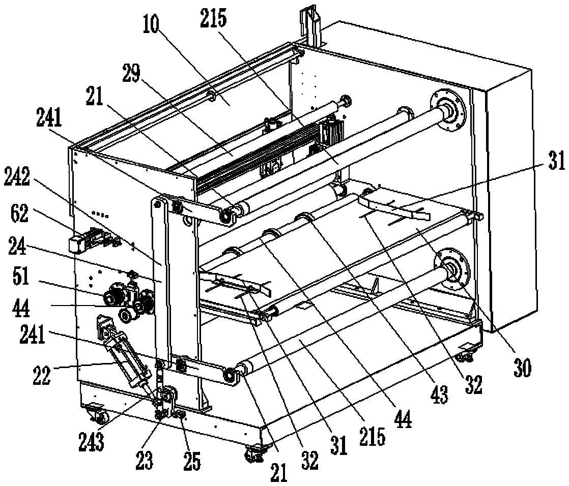
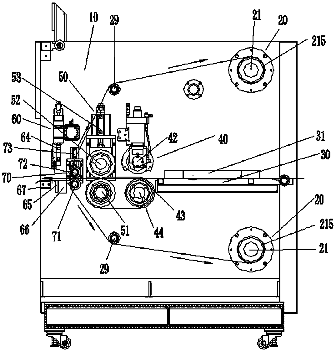
[0038] see Figure 1 to Figure 4 , a slicer, comprising a frame 10, a roll film mechanism 20, and a feeding platform 30 fixed on the frame 10 and arranged in sequence from front to back, a slitting knife mechanism 40, a main drive mechanism 50, a cross-cutting knife Mechanism 60, the film rolling mechanism 20 is fixed on the front part of the frame 10 and is arranged parallel to the upper and lower sides of the feeding platform 30; please refer to Figure 4 , the slitting knife mechanism 40 includes a knife holder 41, a first pneumatic shear knife 42 and a lower cutter drum 44, the two ends of the knife holder 41 are horizontally fixed on the frame 10, and the first Pneumatic shearing knife 42 is fixed on the described knife holder 41, and described following cutter cylinder 44 is fixed on the below of described knife holder 41, and described lower cutter cylinder 44 is connected with described first pneumatic shearing. The corresponding position of the knife 42 is provided w...

Embodiment 2

[0043] The main difference of this embodiment compared with embodiment one is:

[0044] For one, see Figure 5 , the slicer also includes a pressing mechanism 70, the pressing mechanism 70 is arranged between the main driving mechanism 50 and the cross-cutting knife mechanism 60, and the pressing mechanism 70 includes a lower roller 71 and an upper pressing mechanism. Tighten the roller 72, and the upper pressing roller 72 is provided with a pressing force by the first cylinder 73, and the first cylinder 73 is arranged above the upper pressing roller 72; when the main drive mechanism 50 is feeding, the The upper pressing roller 72 is in a loosened state to ensure smooth feeding. When material cutting is required, the upper pressing roller 72 presses the sheet, and the cross-cutting knife mechanism 60 cuts the sheet laterally. After the film is attached to the sheet and passes through the feeding table 30, the slitting knife mechanism 40, the main drive mechanism 50 and the pr...

Embodiment 3

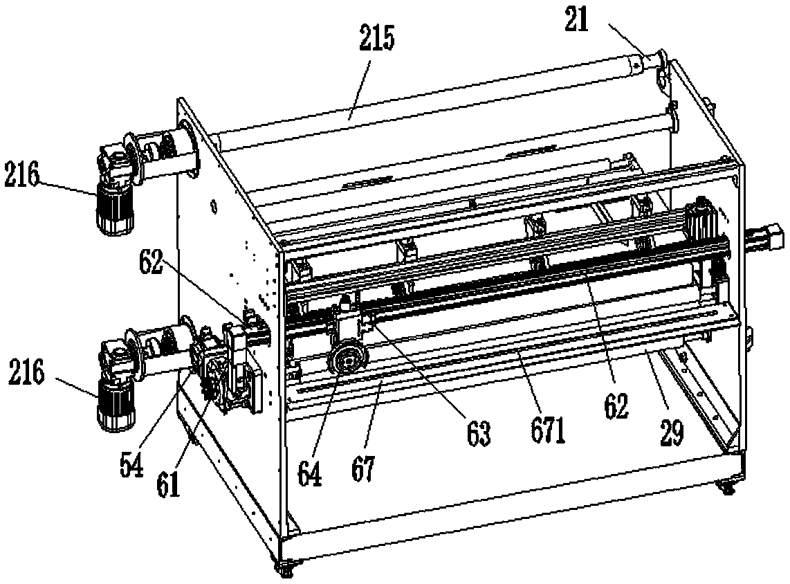
[0051] see Figure 7 to Figure 10 , this embodiment provides a better implementation of the film rolling mechanism, which can overcome the problem that the film rolling shaft 21 shakes or even unhooks due to the pulsation of the air source of the cylinder, so that the swing hook 241 cannot support the shaft end, and there is Potential safety hazards; and when the diameter of the roll film increases, the speed of the roll film is greater than the feeding speed of the main drive mechanism, such as automatic slippage, etc., the details are as follows:

[0052] see figure 1 with Figure 7 , the film roll mechanism 20 includes two film roll shafts 21, a third cylinder 22, a rocker 23, a parallel four-bar linkage mechanism 24 and a limit device 25, and the film roll shaft 21 is sleeved with paper cylinder 215, one end of the third cylinder 22 is installed on one side of the frame 10, and the other end is movably connected with one end of the rocker 23 and the parallelogram mechani...


PUM


Abstract

The invention relates to a sheet cutting machine. The machine comprises a rack, a coiling mechanism, a charging platform, a longitudinal cutting tool mechanism, a main driving mechanism and a transverse cutting tool mechanism, wherein the charging platform, the longitudinal cutting tool mechanism, the main driving mechanism and the transverse cutting tool mechanism are fixed to the rack and sequentially distributed from front to back; the coiling mechanism is fixed to the front part of the rack and is parallel to the charging platform in top and bottom direction; the longitudinal cutting toolmechanism comprises a tool holding rack, a first pneumatic type shearing tool and a lower cutting tool roller; two ends of the tool holding rack are horizontally fixed to the rack; the first pneumaticshearing tool is fixed to the tool holding rack; the lower cutting tool roller is fixed below the tool holding rack; a rolling tool corresponding to the first pneumatic shearing tool is arranged on the lower cutting tool roller; the first pneumatic shearing tool is arranged corresponding to the rolling tool; when in cutting, the first pneumatic shearing tool and the rolling tool are matched to perform longitudinal cutting; the lower cutting tool roller is synchronously driven through the main driving mechanism; a sheet enters the longitudinal cutting tool mechanism through the charging platform and then is lengthways cut.

Description

technical field [0001] The invention relates to a slicer and belongs to the field of slicer. Background technique [0002] The sheet cutting machine involved in the present invention is a device for double-sided film tearing and accurate cutting of similar double-sided film-coated SMC sheets. Existing disclosed sheet cutting machine, such as the publication number is CN102773873A "SMC Sheet Automatic Tear Film Cutting Machine", comprises a tear film feeding device, a cutting device and a sheet taking device, and the tear film feeding device includes installation The upper tearing film roller, the lower tearing film roller, the main film feeding roller and the secondary film feeding roller in the tearing film feeding frame, the upper tearing film roller and the lower tearing film roller cooperate with the upper and lower films, and the main film feeding roller Cooperating with the sheet feeding roller and the intermediate core material, each roller is driven by a servo motor...

Claims


Application Information

Patent Timeline
IPC IPC(8): B26D1/15B26D1/18B26D7/01B32B38/10B65H18/10
CPCB65H18/10B26D1/15B26D1/18B26D7/015B32B38/10B65H2701/19Y02E60/10
Inventor 郑晓东刘思培林洪亮
Owner FUJIAN HAIYUAN AUTOMATIC EQUIP CO LTD
Why Eureka
Try Eureka