
Single-wire cutting machine capable of conducting transverse cutting and longitudinal cutting

A technology of vertical cutting and horizontal cutting, which is applied to fine working devices, manufacturing tools, stone processing equipment, etc., can solve the problems that the worktable can only be fed up and down, low cutting precision, low cutting efficiency, etc., to improve cutting efficiency. , high cutting efficiency, reducing the effect of combined length

Pending Publication Date: 2022-07-01
玉田县昌通电子有限公司
View PDF0 Cites 0 Cited by
  • Summary
  • Abstract
  • Description
  • Claims
  • Application Information

AI Technical Summary

Problems solved by technology

[0002] At present, multi-wire cutting machines are widely used for cutting various hard and brittle materials such as magnetic materials, crystals, ceramics, compounds, oxides, sapphire, and single crystal silicon. Divide into appropriate specifications, sizes and shapes. The existing single-wire cutting machine can only feed up and down when cutting materials, and can only realize cutting in one direction. For some materials that need to be decomposed and cut in multiple directions, it takes more Cutting in one clamping, resulting in low cutting efficiency, low cutting accuracy, labor-intensive and time-consuming

Method used


Image

  • Single-wire cutting machine capable of conducting transverse cutting and longitudinal cutting
  • Single-wire cutting machine capable of conducting transverse cutting and longitudinal cutting
  • Single-wire cutting machine capable of conducting transverse cutting and longitudinal cutting

Examples


Embodiment 1

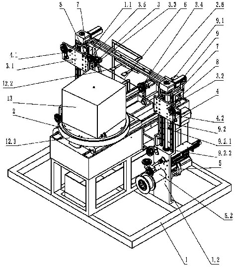
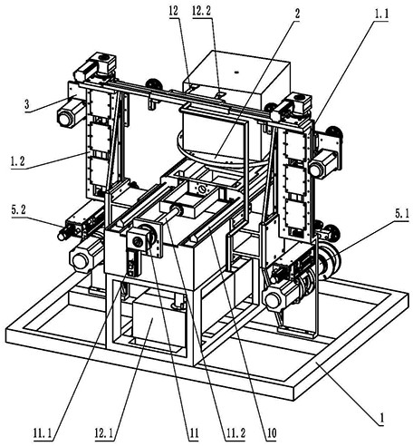
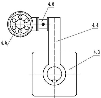
[0029] Embodiment 1, a single wire cutting machine that can cut transversely and longitudinally, such as Figure 1-3 As shown, it includes a base 1, a workbench 2, a cutting assembly 3, a tensioning assembly 4, a wire retracting assembly 5 and a cutting wire 6, characterized in that: the base 1 includes a left column 1.1 and a right column 1.2, the left column 1.1 is fixed on the left side of the base 1, the right column 1.2 is fixed on the right side of the base 1, the left column 1.1 and the right column 1.2 are arranged vertically and parallel, and the left column 1.1 and the right column 1.2 are respectively provided with 2 pieces or 2 pieces With the slide rails 7 arranged in parallel above, the cutting assembly 3 includes a left slide frame 3.1 and a right slide frame 3.2. The left slide frame 3.1 and the right slide frame 3.2 are respectively provided with slide rails 7 on the left column 1.1 and the right column 1.2. The slider 8, the left column 1.1 and the right colu...

Embodiment 2

[0040] like Figure 4 As shown, the worktable 2 includes an upper turntable 2.1 and a lower moving base 2.2, and the upper turntable 2.1 and the lower moving base 2.2 are connected by a rotating shaft 2.3.

[0041] The worktable 2 also includes an upper turntable rotation drive assembly 2.4, the upper turntable rotation drive assembly 2.4 includes a gear 2.4.1 and a rack 2.4.2, the rack 2.4.2 is fixed on the base 1, and the gear 2.4.1 is installed on the base 1. On the rotating shaft 2.3, the gear 2.4.1 meshes with the rack 2.4.2. When the table 2 moves horizontally, the gear 2.4.1 rolls on the rack 2.4.2, driving the upper turntable 2.1 to rotate.

[0042] The upper turntable rotary drive assembly 2.4 also includes a manipulation mechanism 2.4.3, the gear 2.4.1 and the rotating shaft 2.3 are connected by a sliding key, and the manipulation mechanism 2.4.3 can toggle the gear 2.4.1 to slide axially along the rotating shaft 2.3, To achieve the meshing or disengagement of the g...

Embodiment 3

[0047] like Figure 5 As shown, the worktable 2 includes an upper turntable 2.1 and a lower moving base 2.2, and the upper turntable 2.1 and the lower moving base 2.2 are connected by a rotating shaft 2.3.

[0048] The worktable 2 also includes an upper turntable rotation drive assembly 2.4, the upper turntable rotation drive assembly 2.4 includes a gear 2.4.1 and a rack 2.4.2, the rack 2.4.2 is fixed on the base 1, and the gear 2.4.1 is installed on the base 1. On the rotating shaft 2.3, the gear 2.4.1 meshes with the rack 2.4.2. When the table 2 moves horizontally, the gear 2.4.1 rolls on the rack 2.4.2, driving the upper turntable 2.1 to rotate.

[0049] A clutch 2.5 is provided between the gear 2.4.1 and the rotating shaft 2.3.

[0050] The worktable 2 further includes a locking mechanism 2.6, which can lock the upper turntable 2.1 and the lower moving base 2.2.

[0051] The locking mechanism 2.6 can also be installed between the worktable 2 and the base 1 to lock the wo...


PUM


Abstract

The invention relates to the technical field of cutting machines, and relates to a single-wire cutting machine, in particular to a single-wire cutting machine capable of cutting transversely and longitudinally, which comprises a base, a workbench, a cutting assembly, a tensioning assembly, a take-up and pay-off assembly and a cutting wire, the base comprises a left stand column and a right stand column, and the cutting assembly comprises a left sliding frame and a right sliding frame. The workbench is arranged between the left stand column and the right stand column and installed on the base through two or more horizontal guide rails, the workbench can drive a workpiece to horizontally move along the horizontal guide rails, transverse cutting of the workpiece can be achieved, meanwhile, the cutting assembly can vertically move along the left stand column and the right stand column, longitudinal cutting of the workpiece is achieved, and the cutting efficiency is improved. The upper rotating disc and the lower moving seat of the workbench are connected through the rotating shaft, a workpiece can be driven to rotate around the axis of the rotating shaft, multiple types of cutting of the workpiece can be achieved through horizontal, vertical and rotating matched movement and one-time clamping, the application range is wide, and the cutting efficiency is high.

Description

technical field [0001] The invention relates to the technical field of cutting machines, in particular to a single-wire cutting machine, in particular to a single-wire cutting machine capable of transverse cutting and longitudinal cutting. Background technique [0002] At present, the widely used equipment for cutting various hard and brittle materials such as magnetic materials, crystals, ceramics, compounds, oxides, sapphire, and single crystal silicon is multi-wire cutting machine. The existing single-wire cutting machine can only feed up and down when cutting materials, and can only achieve cutting in one direction. When some materials need to be decomposed and cut in multiple directions, more Secondary clamping and cutting results in low cutting efficiency, low cutting precision, and labor and time-consuming. SUMMARY OF THE INVENTION [0003] The present invention provides a single wire cutting machine capable of transverse cutting and longitudinal cutting in view of...

Claims


Application Information

Patent Timeline
IPC IPC(8): B28D5/04B28D7/00B28D7/02
CPCB28D5/045B28D5/0058B28D5/0076
Inventor 章博章雅冬刘素言
Owner 玉田县昌通电子有限公司
Learn More