Injection mold adopting IMR process and application method for injection mold

An injection mold and process technology, applied in the field of IMR process injection mold, can solve the problems of low cost, not as wear-resistant as IMD, short injection molding cycle, etc., and achieve the effect of compact structure, elimination of curling, and reasonable structure design.

Inactive Publication Date: 2018-04-20
乌鲁木齐九品芝麻信息科技有限公司
View PDF1 Cites 7 Cited by
  • Summary
  • Abstract
  • Description
  • Claims
  • Application Information

AI Technical Summary

Problems solved by technology

[0002] The IMR process is to place a part of the continuous sheet in the mold cavity. After injection molding, the plastic will take away the silk screen pattern on the surface of the sheet and separate it from the sheet; IML is to place the transparent sheet with silk screen printing on the back into the mold cavity after molding. After injection molding, it is integrated with the plastic, and the silk screen part is sandwiched between the sheet and the plastic. The process of IMF, INS and IML is similar. The difference is that IMF injects the entire diaphragm with shallow edges, and IML only applies to the local area of ​​the product. Carry out injection molding of film inserts; INS is relative to IMF, which deep-draws the entire film with appearance and then makes it into an insert before injection molding. In the industry, IML / IMF / INS are generally called IMD, and IMR is independent. The difference between IMD and IMR The difference between the finished product is mainly whether there is a layer of transparent material on the surface: IMD has a layer of transparent PC or PET sheet (about 0.1mm), and the pattern is not easy to wear; the surface of IMR is only a layer of ink (thickness can be only a few microns) ), not as wear-resistant as IMD; one advantage of IMR application is that for textured decoration, the pattern is more realistic, the injection molding cycle is short, and the cost is relatively low. It has been widely used in the industry, but the related plastic parts molding theory and Forming equipment cannot achieve zero-defect production for forming the entire diaphragm

Method used


Image

  • Injection mold adopting IMR process and application method for injection mold
  • Injection mold adopting IMR process and application method for injection mold
  • Injection mold adopting IMR process and application method for injection mold

Examples


Embodiment Construction

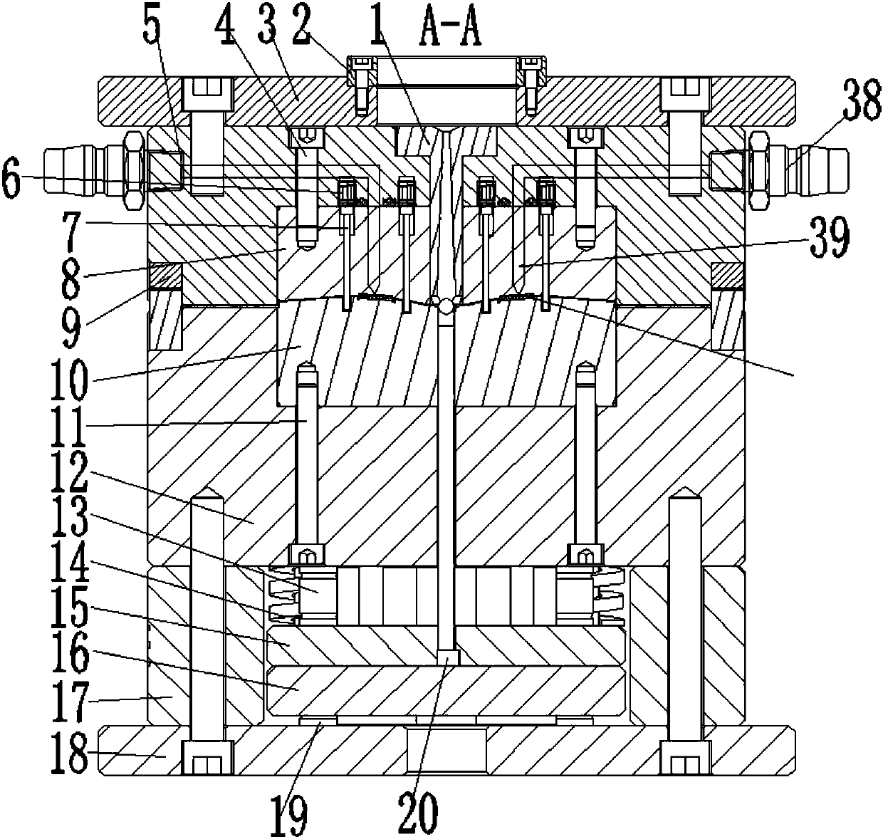
[0023] Figure 1-6 Shown is the relevant explanatory figure of the present invention; Figure 1-6 As shown, an IMR process injection mold:

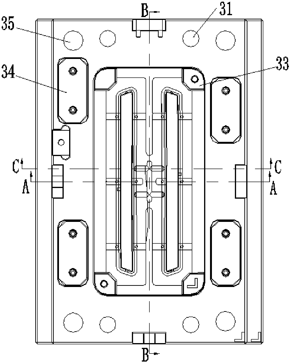
[0024] The mold structure adopts a two-plate mold cold runner injection molding structure, and the layout is one mold with two cavities. The molded parts adopt the insert insert method, mainly including figure 1 The cavity insert 8 and the core insert 10 shown in the cross-section of A-A in the middle, in order to ensure the accuracy of the reset when the cavity insert 8 and the core insert 10 are opened and closed, a matching positioning feature between the two is specially designed Mo Ren Hukou 33.

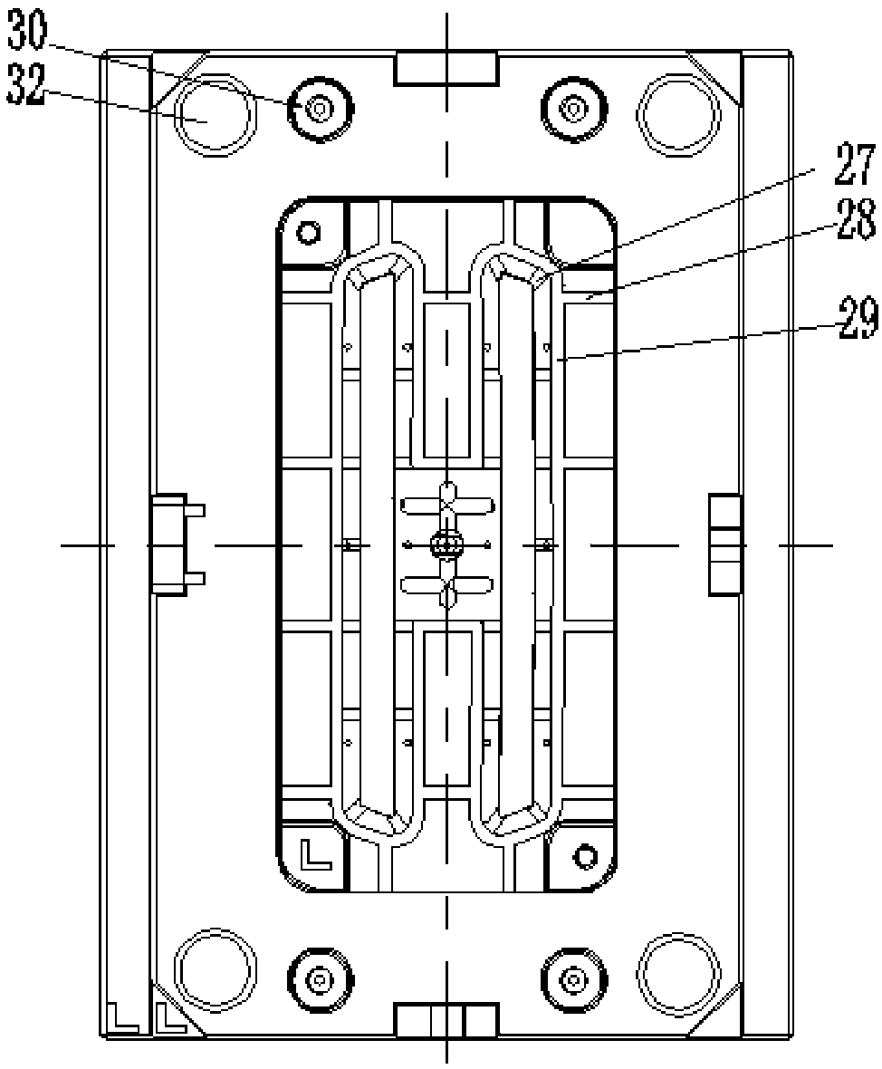
[0025] The mold pouring system adopts the cold runner latent gate pouring method, such as Figure 5 As shown in the cross-sectional view of C-C, a single product adopts the double gate casting method, and the gate of the latent gate is designed on the gate thimble 26, and the gate diameter is The latent gate is beneficial to the autom...


PUM


Abstract

The invention provides an injection mold adopting an IMR process and an application method for the injection mold. The novel injection mold and the application method thereof aim to meet the requirements that products needs to adopt the IMR process for molding. The novel injection mold is designed and has the advantages that a diaphragm positioning mechanism, a mold cavity exhaust mechanism and novel injection molding sprues capable of preventing a diaphragm from being burnt out are structurally and additionally arranged so that the problems of edge curl, uneven shrinkage and deformation in the thin film injection molding process in the IMR process can be solved, the zero-defect and automatic molding production of the products can be realized, and therefore the product forming quality canbe effectively guaranteed, the mold structure and mechanism are novel in design, and the automatic injection molding production of the products can be realized.

Description

technical field [0001] The invention relates to the field of injection mold mechanism design, in particular to an IMR process injection mold and a use method thereof. Background technique [0002] The IMR process is to place a part of the continuous sheet in the mold cavity. After injection molding, the plastic will take away the silk screen pattern on the surface of the sheet and separate it from the sheet; IML is to place the transparent sheet with silk screen printing on the back into the mold cavity after molding. After injection molding, it is integrated with the plastic, and the silk screen part is sandwiched between the sheet and the plastic. The process of IMF, INS and IML is similar. The difference is that IMF injects the entire diaphragm with shallow edges, and IML only applies to the local area of ​​the product. Carry out injection molding of film inserts; INS is relative to IMF, which deep-draws the entire film with appearance and then makes it into an insert bef...

Claims


Application Information

Patent Timeline
Patent Type & Authority Applications(China)
IPC IPC(8): B29C45/14B29C45/27B29C45/34
CPCB29C45/14065B29C45/14688B29C45/14827B29C45/2708B29C45/34
Inventor 不公告发明人
Owner 乌鲁木齐九品芝麻信息科技有限公司
Why Eureka
Try Eureka