Rapid transferring equipment for large products

A product, fast technology, applied in the direction of lifting device, lifting frame, etc., can solve the problems of slow loading and unloading speed, inconvenient loading and unloading, long cycle, etc., to achieve the effect of fast loading and reducing unloading time

Inactive Publication Date: 2018-04-20
刘涔
View PDF7 Cites 4 Cited by
  • Summary
  • Abstract
  • Description
  • Claims
  • Application Information

AI Technical Summary

Problems solved by technology

[0002] At present, in the production process of large-scale products, after the production of the products is completed, the products need to be packaged and processed, and the position and height of the products need to be adjusted. Transport or transfer by purely mechanical transmission means, but the overall cost of the manipulator is high, and it is inconvenient during installation and debugging. When transferring different products, it is necessary to replace the fixed parts of the product; when using a power forklift for transfer, it is flexible. The performance is not strong, and when the production site is small, forklifts cannot perform fast turnover, resulting in greatly reduced production efficiency
[0003] The traditional mechanical transfer device has the following disadvantages: 1. It can only adjust the height of the product, which is equivalent to the direct use of the material hoist, and cannot adjust the placement position of the product on the horizontal plane, and the installation between other processing machinery Inconvenient connection
2. When the weight of the product is too large, loading and unloading is inconvenient, and it is only conveyed through the conveyor belt, which slows down the speed of loading and unloading, and the cycle of single transfer is long, which seriously affects the production efficiency

Method used


Image

  • Rapid transferring equipment for large products
  • Rapid transferring equipment for large products
  • Rapid transferring equipment for large products

Examples


Embodiment Construction

[0021] The following will clearly and completely describe the technical solutions in the embodiments of the present invention with reference to the accompanying drawings in the embodiments of the present invention. Obviously, the described embodiments are only some, not all, embodiments of the present invention. Based on the embodiments of the present invention, all other embodiments obtained by persons of ordinary skill in the art without making creative efforts belong to the protection scope of the present invention.

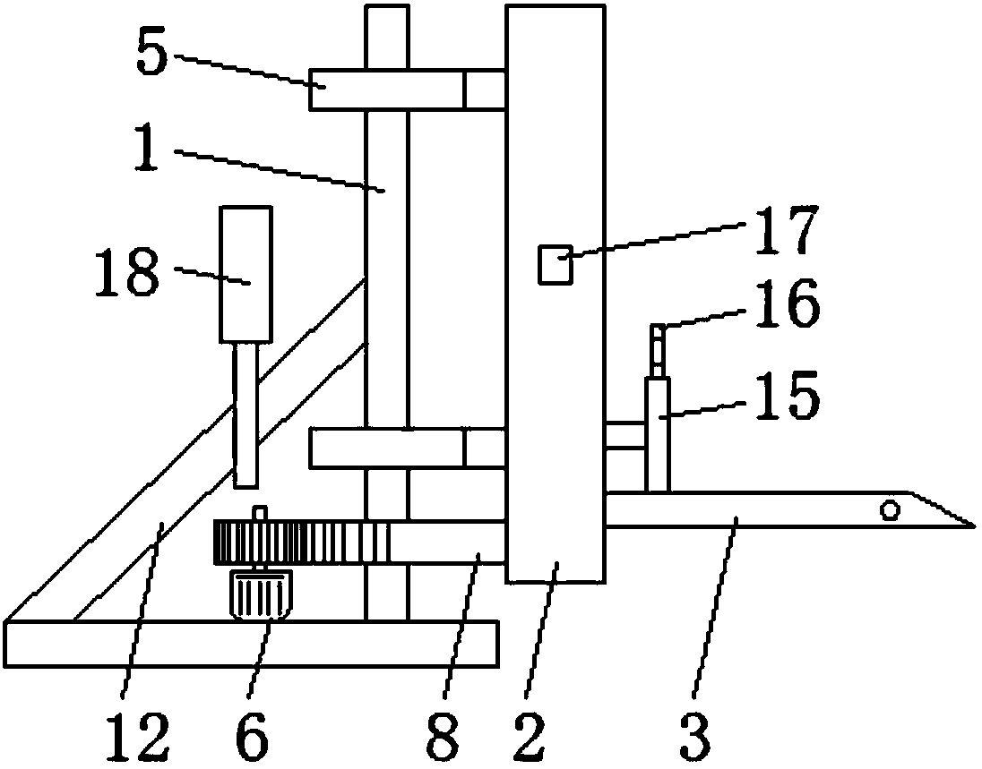
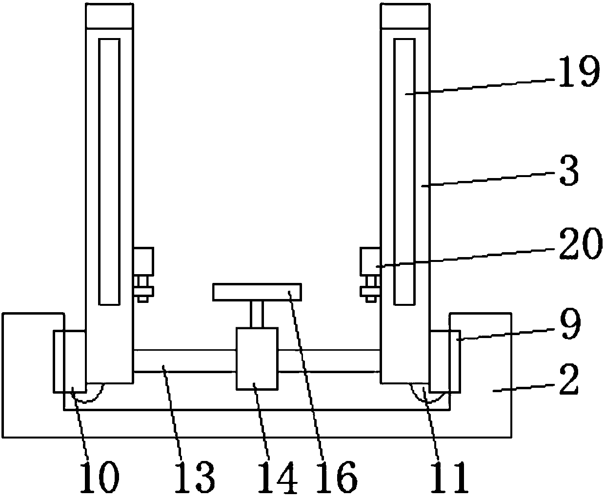
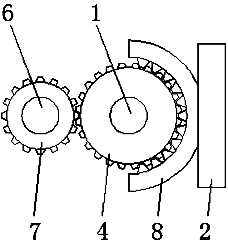
[0022] see Figure 1-3 , the present invention provides a technical solution: a large-scale product rapid transfer equipment, including a central support column 1, a rotating bracket 2, and a lifting arm 3, bearing housings 5 ​​are installed on the upper and lower ends of the central support column 1, and the The central support column 1 is equipped with a driven gear 4 below the lower end bearing seat 5, and the lower end side of the central support column 1 ...


PUM


Abstract

The invention discloses rapid transferring equipment for large products. The rapid transferring equipment comprises a center supporting column, a rotation support and elevating arms. Bearing blocks are arranged at the upper end and the lower end of the center supporting column. A driven gear is arranged below the bearing block at the lower end of the center supporting column. A rotation motor is arranged on one side of the lower end of the center supporting column. An output shaft of the rotation motor is provided with a driving gear. The upper end and the lower end of one side of the rotationsupport are fixedly connected with one sides of the bearing blocks correspondingly. The lower portion of the side, close to the bearing blocks, of the rotation support is fixedly provided with an arcconnecting plate. The inner side of the arc connecting plate is engaged with the driven gear through the arrangement of a tooth groove, and meanwhile the inner side of the rotation support is provided with a sliding installing plate through the arrangement of a guide rail. According to the rapid transferring equipment, when a product is elevated to the target height, the rotation motor is engagedwith the tooth groove so that the rotation support can rotate, and accordingly the containing position of the product is adjusted.

Description

technical field [0001] The invention relates to the technical field of machinery, in particular to a large-scale product rapid transfer equipment. Background technique [0002] At present, in the production process of large-scale products, after the production of the products is completed, the products need to be packaged and processed, and the position and height of the products need to be adjusted. Transport or transfer by purely mechanical transmission means, but the overall cost of the manipulator is high, and it is inconvenient during installation and debugging. When transferring different products, it is necessary to replace the fixed parts of the product; when using a power forklift for transfer, it is flexible. The reliability is not strong, and when the production site is small, forklifts cannot perform fast turnover, resulting in a greatly reduced production efficiency. [0003] The traditional mechanical transfer device has the following disadvantages: 1. It can ...

Claims


Application Information

Patent Timeline
IPC IPC(8): B66F9/02B66F9/04B66F7/16B66F7/28
CPCB66F9/02B66F7/16B66F7/28B66F9/04
Inventor 刘涔李鑫许连高徐寅张余
Owner 刘涔
Why Eureka
Try Eureka