Eureka AIR delivers breakthrough ideas for toughest innovation challenges, trusted by R&D personnel around the world.

Toilet control device and design method

A door control and system device technology, which is applied in the field of bathroom toilets, can solve problems such as gaps, inconvenient installation of pedals, and normal use of the device

Inactive Publication Date: 2018-04-20
ZHEJIANG KEZHUDA MACHINERY TECH CO LTD
View PDF1 Cites 1 Cited by
  • Summary
  • Abstract
  • Description
  • Claims
  • Application Information

AI Technical Summary

Problems solved by technology

[0003] In the disclosed technology, the valve is mainly controlled by gravity. The valve is preferably installed on the ground and controlled by gravity. Moreover, the valve needs to be controlled by a pedal, which is inconvenient to install the pedal. Moreover, the pedal device usually has gaps, so there will be dust Impurities and water entering the gap will affect the normal use of the device, and at the same time, it will also increase the difficulty of cleaning
[0004] Simultaneously existing closet that uses various time-delay valves to control flushing, the complete set of water tanks and valves of the closet disclosed in the above-mentioned patented technology are installed to be transformed, and it is necessary to open holes on both sides of the closet pan or increase the ground height around the closet pan to install gravity. It is very inconvenient to control the valve, and there is usually a lot of noise in construction

Method used


Image

  • Toilet control device and design method
  • Toilet control device and design method
  • Toilet control device and design method

Examples


Embodiment Construction

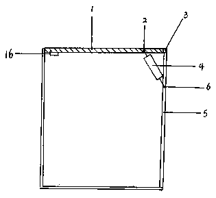
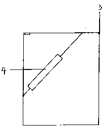
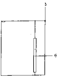
[0037] The squatting door control system device of the present invention includes the squatting door that opens outwards and inwards, and the squatting door that moves and opens along the plane where the squatting door is located.

[0038]The first case: the outwardly opened squatting door control system device includes: squatting door 1, squatting wall 5, door shaft 3, first cylinder 4, medium pipeline 8, second cylinder 9, valve pull rod 10 , the squatting door is connected to the wall of the squatting position through the door shaft, and the first cylinder includes a cylinder wall, a first pull rod 12, and a first piston 13, and the first pull rod is connected with the first piston to pass through the top of the cylinder, and the first pull rod There is a first connection point 2 at the top, a second connection point 6 at the bottom of the first cylinder, a first movable rotating connection point for the squatting door, a first fixed rotating connecting point for the squatti...


PUM


Abstract

The invention discloses a toilet control device. The device includes: a squatting door, a squatting wall, a first cylinder, a medium pipeline, a second cylinder, a valve pull rod, the first cylinder includes a cylinder wall, a first pull rod, a first piston, the first pull rod and the first The piston is connected through the cylinder, the top of the first pull rod has a first connection point, and the bottom of the first cylinder has a second connection point, and the two connection points are respectively connected to the squatting door and the squatting wall, and the squatting door and the squatting wall are connected to the The two connection points of the first cylinder are connected by the rotating shaft. The bottom of the first cylinder and the top of the second cylinder are connected through a medium pipeline, and the bottom of the first cylinder and the top of the second cylinder are connected with the medium pipeline. For liquid medium, the valve pull rod penetrates into the second cylinder and connects with the second piston.

Description

technical field [0001] The invention belongs to the field of toilets, in particular to a squatting door for controlling flushing of the toilet. Background technique [0002] The invention relates to a control valve of a toilet water tank in the patent application whose publication number is CN 104264756A. [0003] In the disclosed technology, the valve is mainly controlled by gravity. The valve is preferably installed on the ground and controlled by gravity. Moreover, the valve needs to be controlled by a pedal, which is inconvenient to install the pedal. Moreover, the pedal device usually has gaps, so there will be dust Impurities and water entering the gap will affect the normal use of the device, and at the same time, it will also increase the difficulty of cleaning. [0004] Simultaneously existing closet that uses various time-delay valves to control flushing, the complete set of water tanks and valves of the closet disclosed in the above-mentioned patented technol...

Claims


Application Information

Patent Timeline
IPC IPC(8): E03D5/06E03D5/012E03D11/10
CPCE03D5/06E03D5/012E03D11/10
Inventor 王永强
Owner ZHEJIANG KEZHUDA MACHINERY TECH CO LTD
Why Eureka
Eureka Blog
Learn More