
A punching machine for electric cement pole construction

A technology of cement rod and punching machine, applied in the field of electric power, can solve problems such as motor burnout, and achieve the effect of improving practicability

Active Publication Date: 2019-09-20
江苏正苏基础工程有限公司
View PDF5 Cites 0 Cited by
  • Summary
  • Abstract
  • Description
  • Claims
  • Application Information

AI Technical Summary

Problems solved by technology

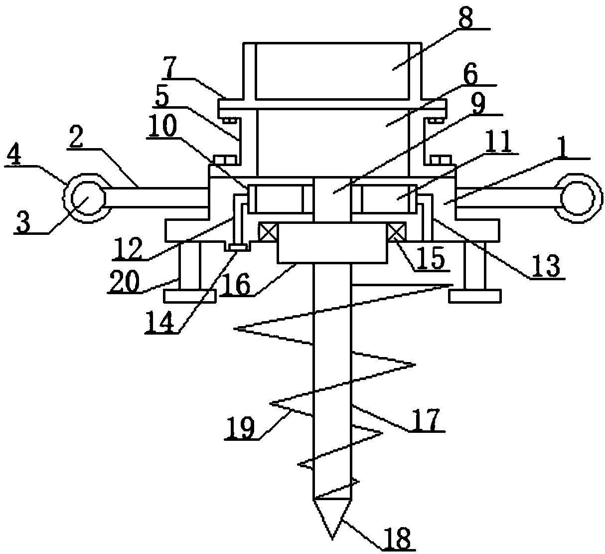
[0002] At present, when installing electric cement poles, it is necessary to bury the bottom of the cement poles in the ground, so a puncher has to be used, and the rotating spindle driven by the motor of a general puncher is fixedly connected to the motor. , once the rotating blade encounters a hard geological situation, it is likely to cause the motor to burn out

Method used


Image

  • A punching machine for electric cement pole construction
  • A punching machine for electric cement pole construction
  • A punching machine for electric cement pole construction

Examples


Embodiment Construction

[0017] The following will clearly and completely describe the technical solutions in the embodiments of the present invention with reference to the accompanying drawings in the embodiments of the present invention. Obviously, the described embodiments are only some, not all, embodiments of the present invention. Based on the embodiments of the present invention, all other embodiments obtained by persons of ordinary skill in the art without making creative efforts belong to the protection scope of the present invention.

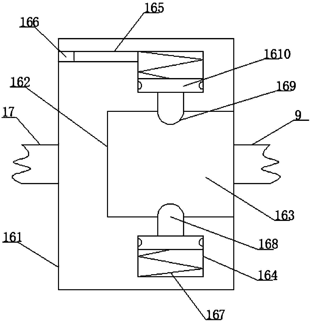
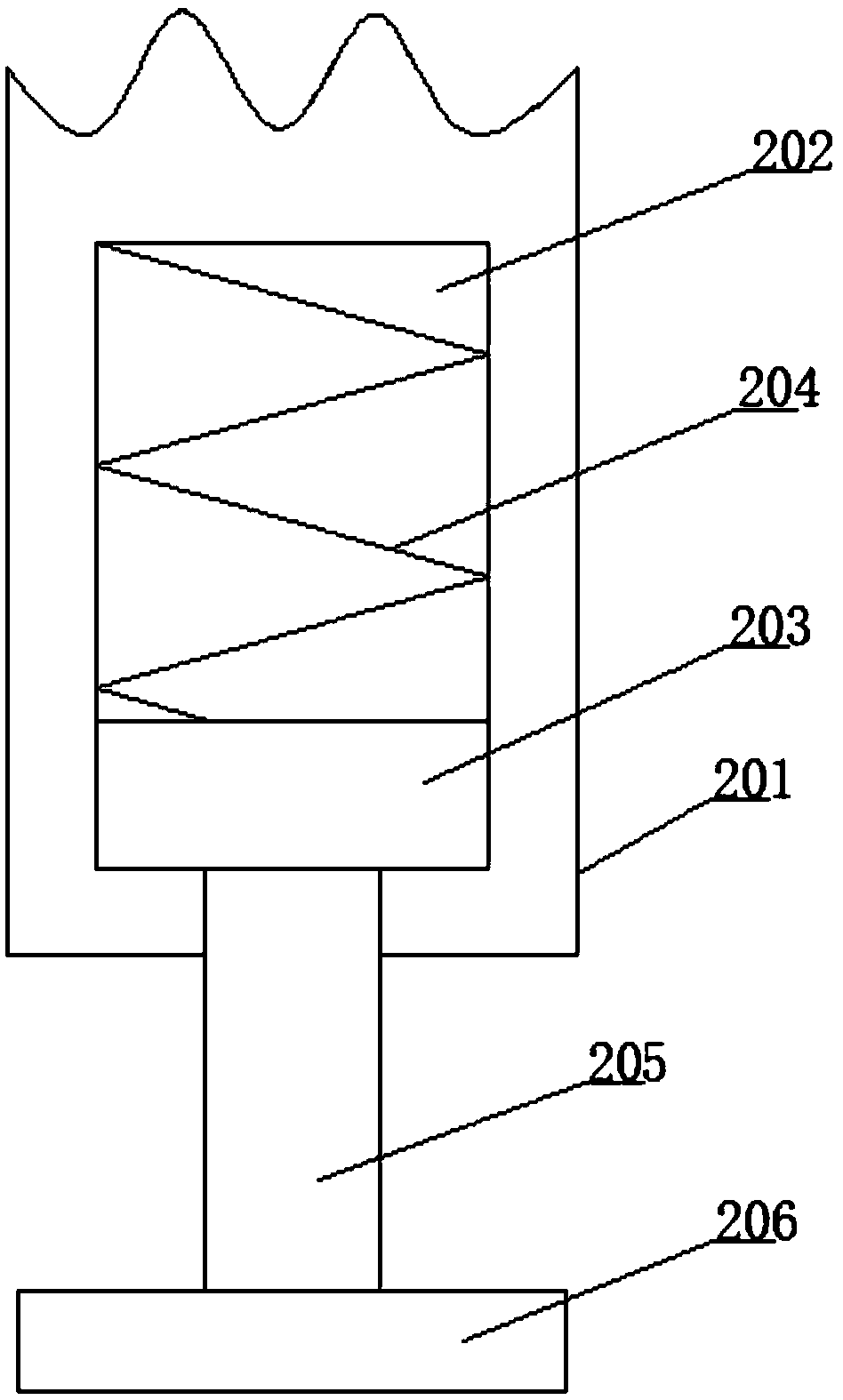
[0018] see figure 1 , an embodiment provided by the present invention: includes a bottom hollow shell 1, a plurality of integrated connecting rods 2 are arranged on the side of the bottom hollow shell 1, and a ring-shaped ring is fixed at the ends of a plurality of connecting rods 2 Rod 3, the outer surface of the annular rod 3 is sleeved with a leather sheath 4, the top of the bottom hollow shell 1 is fixed with a motor mounting shell 5 by bolts, and an inver...


PUM


Abstract

The invention discloses a perforating machine for cement electricity pole construction. The perforating machine comprises a bottom hollow shell, the side face of the bottom hollow shell is provided with a plurality of integrated connecting poles, and an annular pole is fixed to each end of the multiple connecting poles. The outer surfaces of the annular poles are each sleeved with a leather sleeve, and a motor mounting shell is fixed to the top of the bottom hollow shell through bolts. The motor mounting shell is internally provided with an inverted motor, and a power supply fixing shell is fixed to the top of the motor mounting shell through bolts. According to the perforating machine, the effective perforating effect can be achieved on the ground, the perforating machine is provided withan air-type overloading protection mechanism, the controllability is achieved, the motor can be effectively protected to the largest extent, and the burning-out phenomenon of the motor is avoided; and additionally, when a screw blade is stuck into the underground, the unavoidable situation is encountered, through the air pressure, the final remedial measure can be implemented, thus the perforating machine has an emergency dealing function, and the practicability of the perforating machine is improved.

Description

technical field [0001] The invention relates to the technical field of electric power, in particular to a punching machine for electric cement pole construction. Background technique [0002] At present, when installing electric cement poles, it is necessary to bury the bottom of the cement poles in the ground, so a puncher has to be used, and the rotating spindle driven by the motor of a general puncher is fixedly connected to the motor. , once the rotating blade encounters a hard geological situation, it is likely to cause the motor to burn out. Contents of the invention [0003] The object of the present invention is to provide a punching machine for electric cement pole construction to solve the problems raised in the above-mentioned background technology. [0004] In order to achieve the above object, the present invention provides the following technical solutions: a drilling machine for electric cement pole construction, comprising a bottom hollow shell, the side o...

Claims


Application Information

Patent Timeline
Patent Type & Authority Patents(China)
IPC IPC(8): E21B3/02E21B17/22H02K11/20
Inventor 杨国亭
Owner 江苏正苏基础工程有限公司
Learn More