Portable folding type lifting target

A foldable and portable technology, applied in the field of gun shooting training, can solve the problems of lack of flexibility and actual combat training, and inconvenient carrying of shooting targets, and achieve the effect of solving site restrictions and improving application space

Pending Publication Date: 2018-04-20
成都高阳信息技术有限公司
View PDF5 Cites 9 Cited by
  • Summary
  • Abstract
  • Description
  • Claims
  • Application Information

AI Technical Summary

Problems solved by technology

[0005] The purpose of the present invention is to overcome the deficiencies of the prior art, and the purpose is to provide a portable folding lifting target, which solves the problems of inconvenient carrying of the training shooting target, lack of flexibility and practical training

Method used


Image

  • Portable folding type lifting target
  • Portable folding type lifting target
  • Portable folding type lifting target

Examples


Embodiment 1

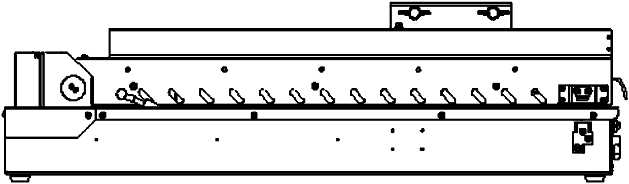
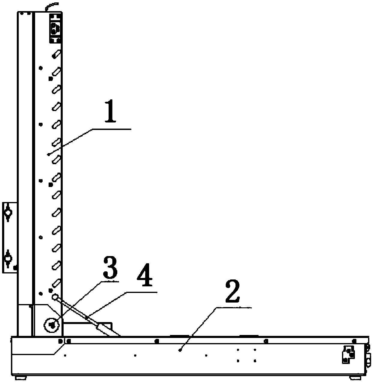
[0035] Such as Figure 1-5 As shown, a portable folding lifting target of the present invention includes a lifting bracket 1 and a supporting base 2, the bottom end of the lifting bracket 1 is connected and installed on the front end of the supporting base 2 through a rotating shaft 3, and the lifting bracket 1 and the supporting base 2 The piston rod 4 provided therebetween can be telescopically controlled by the piston rod 4 to rotate the lifting bracket 1 around the rotating shaft 3 to realize folding or unfolding; it solves the inconvenience of carrying the training shooting target. In practical applications, pulleys, traction handles, and charging ports can be provided at the bottom of the support base 2 as required. In order to realize the independent operation ability and degree of automation of the portable lifting target.

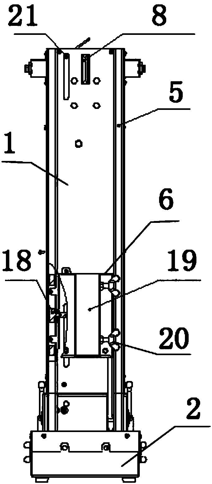
[0036] The outer side of the lift bracket 1 is provided with a guide groove 5, the guide groove 5 is provided with a lift platform 6, the lift pl...

Embodiment 2

[0047] Such as Figure 1-6 As shown, the present invention is a portable folding lifting target. On the basis of Embodiment 1, a sensor 21 is provided on the outer side of the lifting bracket 1 to sense the lifting movement of the lifting platform 6 . The functional principle of the sensor 21 is similar to the induction principle of the elevator door. It mainly detects the lifting action of the lifting platform 6 and determines the lifting height. In actual design, the shooting target frame 7 can be designed as an electronic target, so that the target can be remotely monitored. In some cases, the shooting data is transmitted to the control terminal 27 by the controller 22, and the control terminal 27 can be a dedicated terminal, or can be replaced by a mobile phone or a computer.

[0048] The support base 2 is provided with a controller 22 , and the controller 22 is connected with the sensor 21 for control.

[0049] The controller 22 includes a communication module 23, a cont...


PUM


Abstract

The invention discloses a portable folding type lifting target. The bottom end of a lifting support is mounted at the front end of a supporting base in a connected manner through a rotating shaft, a piston rod is arranged between the lifting support and the supporting base, and the piston rod stretches and retracts to control the lifting support to rotate around the rotating shaft so as to fold orunfold the lifting target; and a guiding groove is formed in the outer side of the lifting support, a lifting platform is arranged in the guiding groove, a shooting target frame is inserted in the lifting platform, an upper pulley block is arranged at the upper end of the inner side of the lifting support, a lower pulley block is arranged on the inner side of the lifting support, a driving motoris arranged in the front end of the supporting base, and drives an output rotating shaft to rotate through a gearbox, hoisting pulleys are separately arranged at two ends of the output rotating shaft,the upper end of the lifting platform is connected with a hoisting rope, after the hoisting rope is wound through the upper pulley block, the tail end of the hoisting rope is forwards wound on one ofthe hoisting pulleys, the lower end of the lifting platform is connected with a descending rope, and after the descending rope is wound through the lower pulley block, the tail end of the descendingrope is reversely wound on the other hoisting pulley.

Description

technical field [0001] The invention relates to the technical field of gun shooting training, in particular to a portable folding lifting target. Background technique [0002] In the daily training of the troops, shooting is an essential training item. The target drone is a training equipment often used in shooting training in military military training. The purpose is to provide objective and accurate standard conditions for shooting training, assessment, and competition, which is conducive to improving the accuracy of live ammunition shooting. [0003] The shooting targets usually used in shooting training are fixed targets, and there are also lifting targets. Due to the complex and changeable actual application environment, the existing fixed targets or lifting targets are not convenient for transportation and quick installation. In live ammunition training, due to their mobile The performance is poor, it is difficult to place in various environments or terrains for trai...

Claims


Application Information

Patent Timeline
Patent Type & Authority Applications(China)
IPC IPC(8): F41J1/10F41J7/00
CPCF41J1/10F41J7/00
Inventor 李远彦杜雨寒
Owner 成都高阳信息技术有限公司
Why Eureka
Try Eureka