
Infrared calibration light source used under vacuum low-temperature condition

A vacuum low temperature, calibration technology, applied in the field of calibration and calibration, infrared radiation measurement, can solve the problem of less calibration points and so on

Active Publication Date: 2018-04-20
BEIJING ZHENXING METROLOGY & TEST INST
View PDF6 Cites 2 Cited by
  • Summary
  • Abstract
  • Description
  • Claims
  • Application Information

AI Technical Summary

Problems solved by technology

[0009] The purpose of the present invention is to overcome the deficiencies of the prior art, and provide an infrared calibration light source applied under vacuum and low temperature conditions, which can solve the problem of few calibration points in the traditional orbital radiation parameter calibration process

Method used


Image

  • Infrared calibration light source used under vacuum low-temperature condition
  • Infrared calibration light source used under vacuum low-temperature condition
  • Infrared calibration light source used under vacuum low-temperature condition

Examples


Embodiment Construction

[0030] Specific embodiments of the present invention will be described in detail below in conjunction with the accompanying drawings. In the following description, for purposes of explanation and not limitation, specific details are set forth in order to provide a thorough understanding of the invention. It will be apparent, however, to one skilled in the art that the present invention may be practiced in other embodiments that depart from these specific details.

[0031] It should be noted here that, in order to avoid obscuring the present invention due to unnecessary details, only the device structure and / or processing steps closely related to the solution according to the present invention are shown in the drawings, and the steps related to the present invention are omitted. Invent other details that don't really matter.

[0032] The embodiment of the present invention provides an infrared calibration light source applied under vacuum and low temperature conditions. The in...


PUM


Abstract

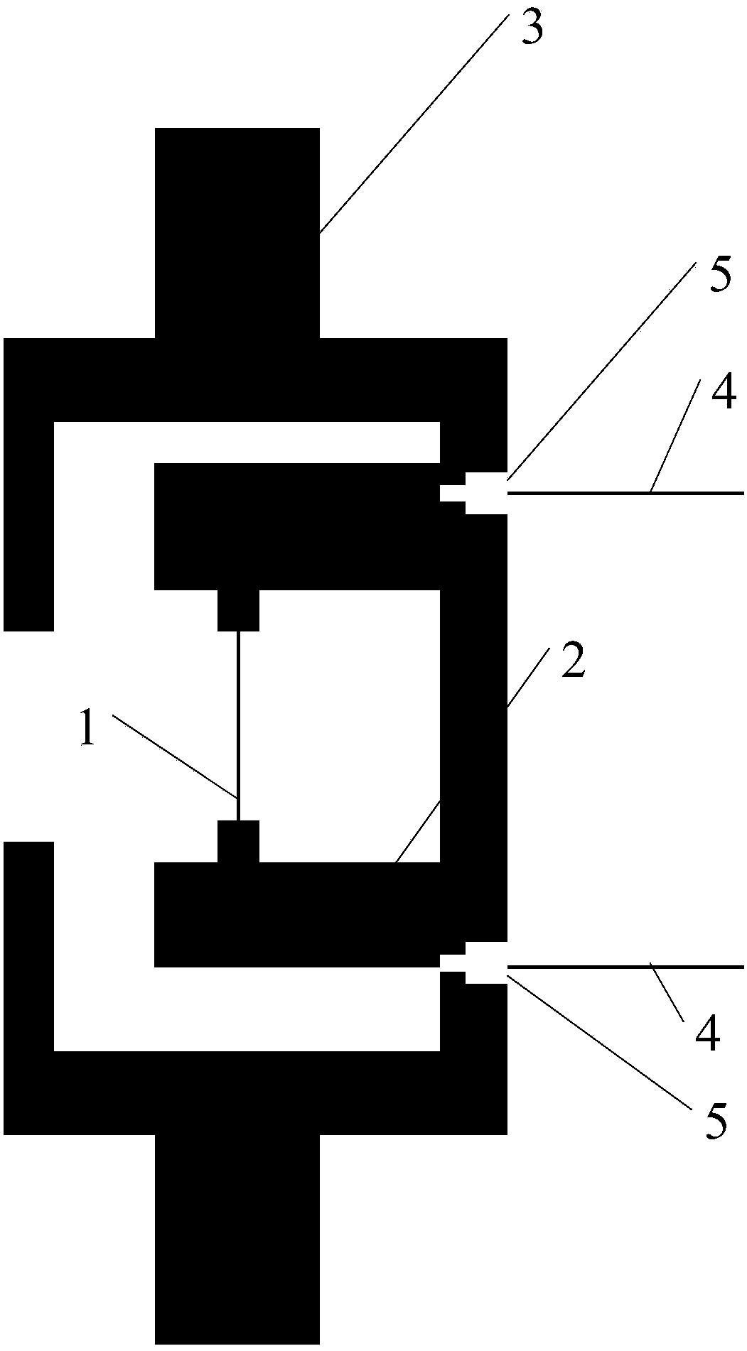
The invention relates to an infrared calibration light source used under a vacuum low-temperature condition. The infrared calibration light source mainly comprises a shell, a mechanical installation interface, a black-body radiation surface, a supporting structure, a vacuum encapsulation window and power supply lines; the black-body radiation surface is placed inside the shell; a circular diaphragm above a black-body radiation film is arranged at the top of the shell; the black-body radiation surface is parallel to a plane where the diaphragm is located; holes for allowing the power supply lines to pass are formed in the shell; the outer surface of the shell has a high emissivity; the inner surface of the shell has a low emissivity; a surface of the black-body radiation film, which directly faces the diaphragm, is adopted as the black-body radiation surface, has a high emissivity and is used for emitting infrared radiation; the other surface of the black-body radiation film has a low emissivity; the supporting structure is made of a high temperature-resistance and low-thermal conductivity ceramic material; and the power supply lines are used for supplying power for the black-body radiation surface so that the temperature of the black-body radiation surface can be controlled.

Description

technical field [0001] The invention relates to the technical field of infrared radiation measurement, calibration and calibration, in particular to an infrared calibration light source applied under vacuum and low temperature conditions. Background technique [0002] At present, with the development of technology, the application of infrared imagers has been extended to near space and outer space. With the gradual improvement of the technical and tactical performance requirements of these infrared payloads, high-precision quantitative detection has become an inevitable trend for the further development of infrared payloads. [0003] Radiation parameter calibration is the basis and prerequisite for quantitative detection of infrared loads. Through radiation parameter calibration, the radiation value of the target can be quantitatively detected, so that the infrared load can judge the type of target through the radiation value, which greatly improves the infrared load. The d...

Claims


Application Information

Patent Timeline
Patent Type & Authority Applications(China)
IPC IPC(8): G01J5/52G01J5/08
CPCG01J5/0896G01J5/80G01J5/53
Inventor 张玉国吴柯萱孙红胜魏建强宋春晖
Owner BEIJING ZHENXING METROLOGY & TEST INST
Learn More